PS288_OwnersMnl_PriorTo2009 - 第37页
Set Up • Making the Necessary Connections PS288 Owner’s Manual 2—3 Socket Opener Pressur e Contro l— NOTE: The Socket Actuator must be switched on fr om the AH500 softwar e before the r egulator g auge will display a r e…
Set Up • Making the Necessary Connections
2—2 PS288 Owner’s Manual
Pneumatic Input and Controls
The PS288 requires clean, dry, oil-free air from an industrial grade compres-
sor. The compressor’s tank should be of sufficient size to maintain constant
air pressure at 85 liters per minute (3 Standard Cubic Feet per Minute).
NOTE: If the compressor cannot maintain the correct air pressure,
system performance will be affected.
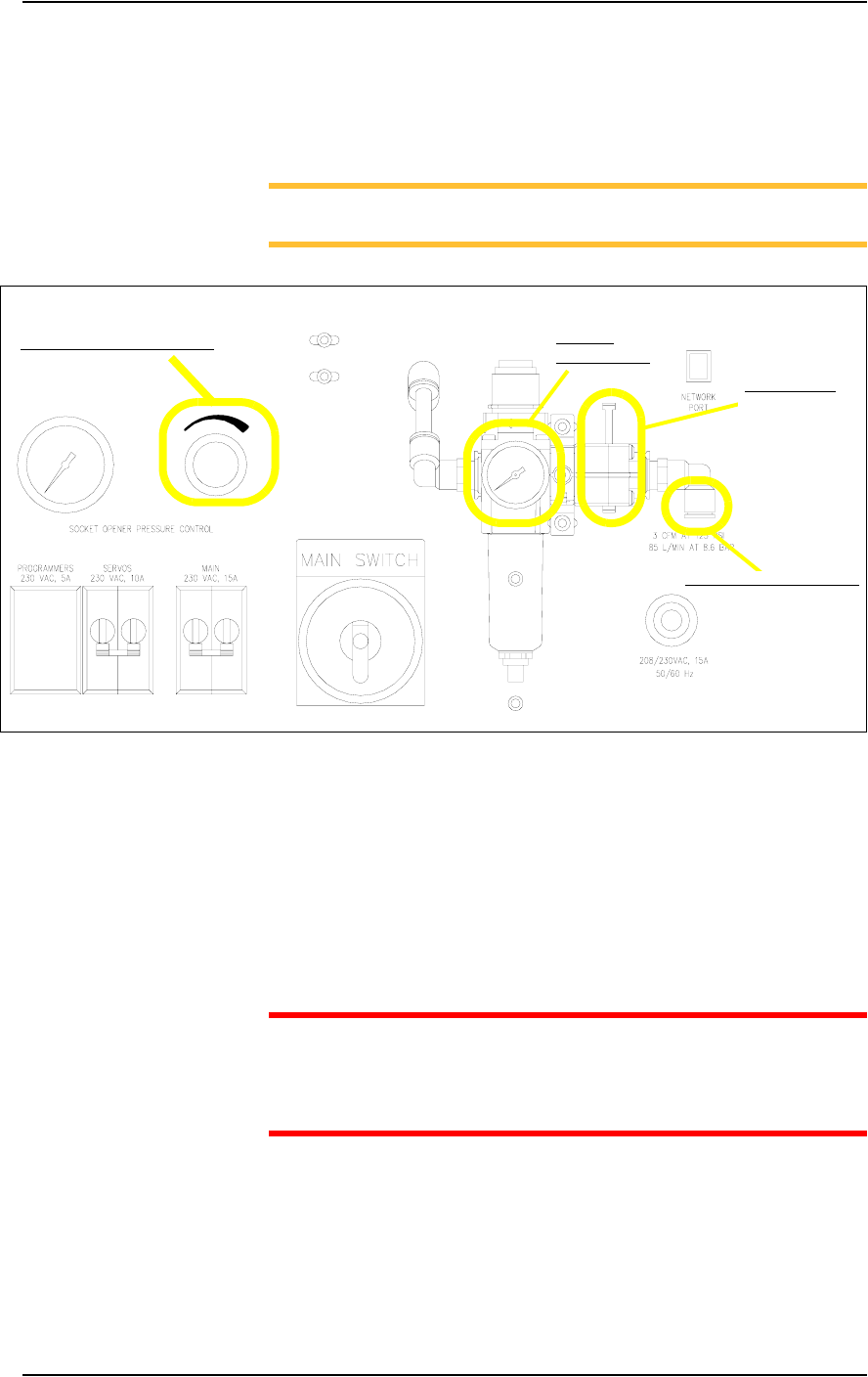
Figure 2-1—Pneumatic input and controls on the input panel
External Air Line Connection—
The low pressure air source is supplied to the system through the external air
line connected to the air filter. The PS288 air filter is a secondary filter only.
The main filter should be a 10 micron filter/regulator installed between the
factory compressor and the PS288. The external air line should be at least
3 meters (10 feet) long to allow the supplied air to cool sufficiently so that
water vapor contained in the air condenses and can be extracted. See Figure
2-1 for the location of the external air line connection.
CAUTION: Oil, excessive moisture, or poorly filtered air will
obstruct the system’s internal air network, affect performance, and
void the warranty related to air system failure. If oil or excessive
moisture is detected, call Data I/O Customer Support immediately.
Main Air Pressure Gauge—
The main air pressure gauge displays the air pressure the PS288 uses inter-
nally to generate vacuum and air operations. The main pressure regulator is
pre-set to 586 kiloPascals (85 PSI) as read on the gauge on the input panel.
This setting is not adjustable. See Figure 2-1 for the location of the main air
pressure gauge.
Main air
pressure gauge
Socket opener pressure control
External air line connection
Main air valve
Set Up • Making the Necessary Connections
PS288 Owner’s Manual 2—3
Socket Opener Pressure Control—
NOTE: The Socket Actuator must be switched on from the AH500
software before the regulator gauge will display a reading.
The socket opener pressure control, also on the input panel, controls the air
pressure used to lower the Socket Actuator that opens the socket(s). This
pressure should remain in the range of 138-276 kiloPascals (20–40 PSI) but
may be adjusted within that range depending on the socket in use. See Fig-
ure 2-1 for the location of the socket opener pressure control.
NOTE: See “Adjusting the Socket Actuator Air Pressure” on page
5-37 for more information.
Electrical Input
Required power is provided through a customer-supplied 3 wire power cable
with one end terminated in an electrical plug as required by the customer’s
facility. Data I/O trained personnel route the other end of the 3 wire power
cable through the input panel and screw it into a terminal block inside the
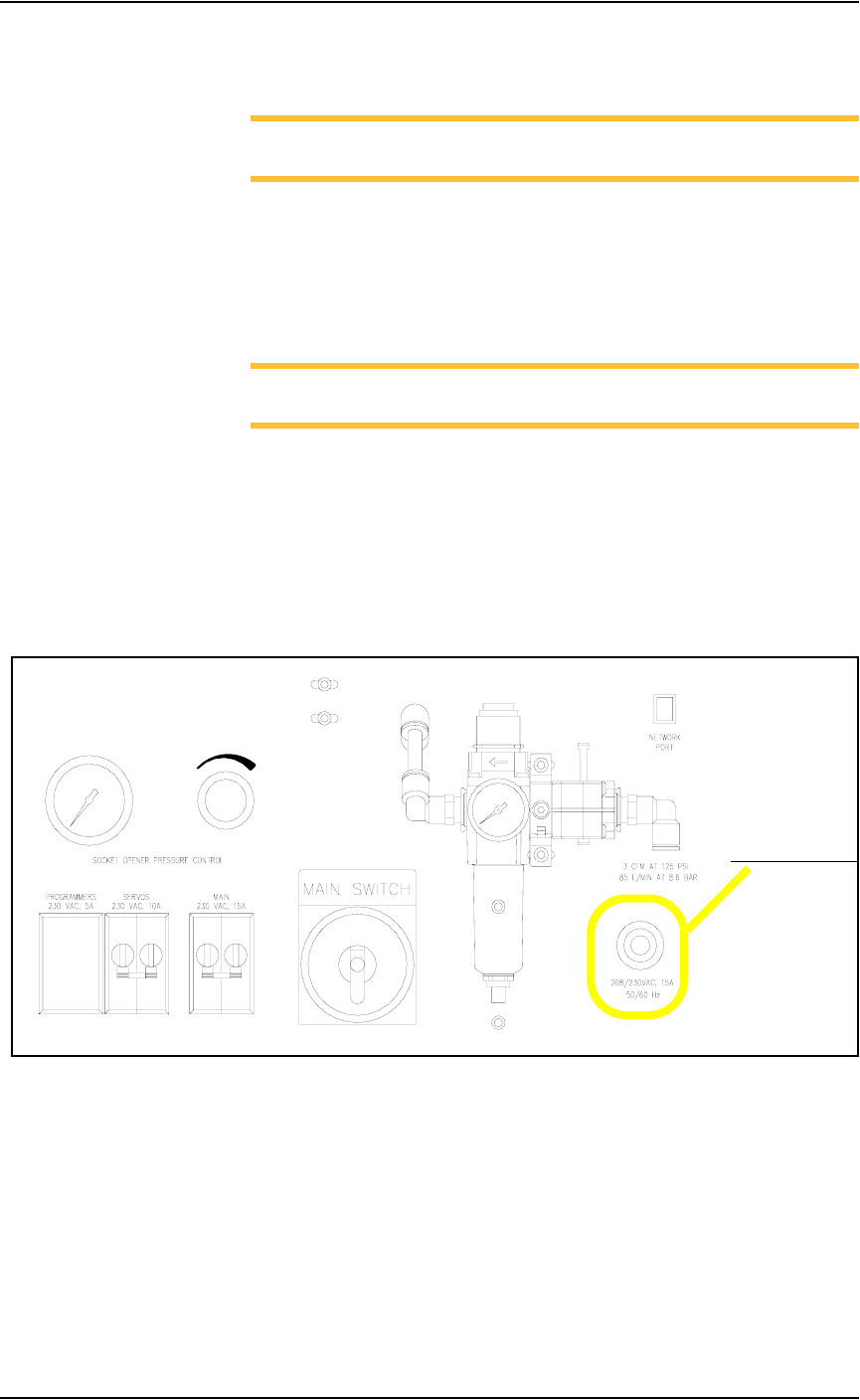
PS288. See Figure 2-2 for the power cable routing through the input panel.
.
Figure 2-2—Power cable routing through input panel
Power cable routing
Set Up • Applying Power for the First Time
2—4 PS288 Owner’s Manual
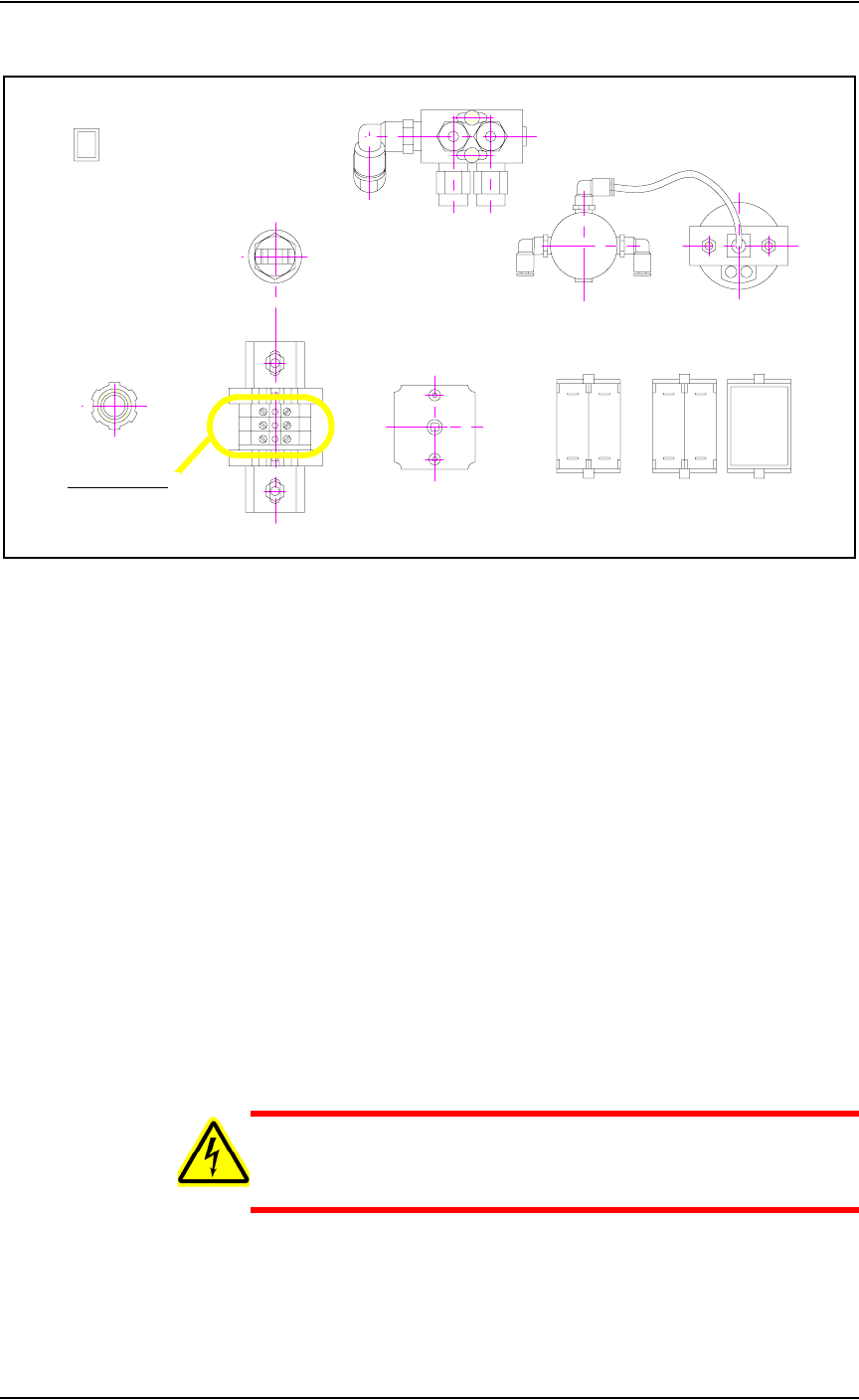
See Figure 2-3 for the terminal block where the 3 wire cable is attached.
Figure 2-3—Terminal block
Applying Power
for the First
Time
Before the PS288 is switched on the first time, ensure the following:
) The external air line is connected, and the main air valve is open.
) All E-Stop buttons are in the released (operating) positions (refer to
Figure 1-2 for location of the E-Stop buttons).
) All safety shields are closed (refer to Figure 1-2 for location of the
safety shields).
) The circuit breakers on the input panel on the back of the PS288 are in
the ON (i.e., UP) position.
) The circuit breaker on the I/O Controller is set to the ON position.
) The power switch on the Handler Computer is set to the ON position.
) The Socket Adapters required for the job have been installed on all
necessary programmer sites. See “(Optional) Change a Socket
Adapter” on page 3-17 for more information.
Once the above conditions have been checked, turn the main power switch
on the input panel (on the rear of the PS288) in a clockwise direction to the
ON position. Then press the I/O Controller START button.
WARNING: Electric shock hazard. Power is applied to the pro-
grammer assemblies when the main power switch is switched on,
even when the I/O Controller is turned off.
After power is applied, verify that all mechanical assemblies appear to be at
rest, and no obvious failures or electrical anomalies occur. Verify that the
Handler Computer boots properly and is waiting at a network login window.
Terminal block