PS288_OwnersMnl_PriorTo2009 - 第38页
Set Up • Applyin g Power for the First Tim e 2—4 PS288 Owner’s Manual See Figur e 2-3 for the terminal block where the 3 wire cable is attache d. Figur e 2-3—T erminal block Applying Power for the First Ti m e Before the…
Set Up • Making the Necessary Connections
PS288 Owner’s Manual 2—3
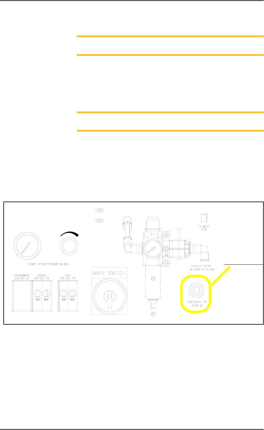
Socket Opener Pressure Control—
NOTE: The Socket Actuator must be switched on from the AH500
software before the regulator gauge will display a reading.
The socket opener pressure control, also on the input panel, controls the air
pressure used to lower the Socket Actuator that opens the socket(s). This
pressure should remain in the range of 138-276 kiloPascals (20–40 PSI) but
may be adjusted within that range depending on the socket in use. See Fig-
ure 2-1 for the location of the socket opener pressure control.
NOTE: See “Adjusting the Socket Actuator Air Pressure” on page
5-37 for more information.
Electrical Input
Required power is provided through a customer-supplied 3 wire power cable
with one end terminated in an electrical plug as required by the customer’s
facility. Data I/O trained personnel route the other end of the 3 wire power
cable through the input panel and screw it into a terminal block inside the
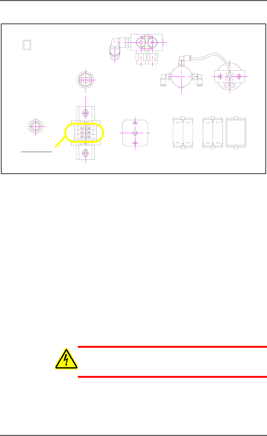
PS288. See Figure 2-2 for the power cable routing through the input panel.
.
Figure 2-2—Power cable routing through input panel
Power cable routing
Set Up • Applying Power for the First Time
2—4 PS288 Owner’s Manual
See Figure 2-3 for the terminal block where the 3 wire cable is attached.
Figure 2-3—Terminal block
Applying Power
for the First
Time
Before the PS288 is switched on the first time, ensure the following:
) The external air line is connected, and the main air valve is open.
) All E-Stop buttons are in the released (operating) positions (refer to
Figure 1-2 for location of the E-Stop buttons).
) All safety shields are closed (refer to Figure 1-2 for location of the
safety shields).
) The circuit breakers on the input panel on the back of the PS288 are in
the ON (i.e., UP) position.
) The circuit breaker on the I/O Controller is set to the ON position.
) The power switch on the Handler Computer is set to the ON position.
) The Socket Adapters required for the job have been installed on all
necessary programmer sites. See “(Optional) Change a Socket
Adapter” on page 3-17 for more information.
Once the above conditions have been checked, turn the main power switch
on the input panel (on the rear of the PS288) in a clockwise direction to the
ON position. Then press the I/O Controller START button.
WARNING: Electric shock hazard. Power is applied to the pro-
grammer assemblies when the main power switch is switched on,
even when the I/O Controller is turned off.
After power is applied, verify that all mechanical assemblies appear to be at
rest, and no obvious failures or electrical anomalies occur. Verify that the
Handler Computer boots properly and is waiting at a network login window.
Terminal block
Set Up • Setting Up Static Tray Input/Output
PS288 Owner’s Manual 2—5
If electrical or mechanical problems are noted, turn off the PS288 and notify
Data I/O Customer Support immediately.
Setting Up
Static Tray
Input/Output
Static tray input and output is the standard configuration on the PS288.
NOTE: When using static tray input and output, ensure that blank
devices are loaded with the correct pin 1 orientation. Pin 1 orienta-
tion is set when the PNP head locations are taught. For more infor-
mation, see “Teach Tray Locations” on page 3-38.
To set up the static tray input and output:
1. Prepare system—
1a) If a job is running, press Pause on the Run window.
1b) Press Exit to return to the Setup window.
1c) Click the Options tab.
1d) Open the front safety shield.
2. Install Static Trays—
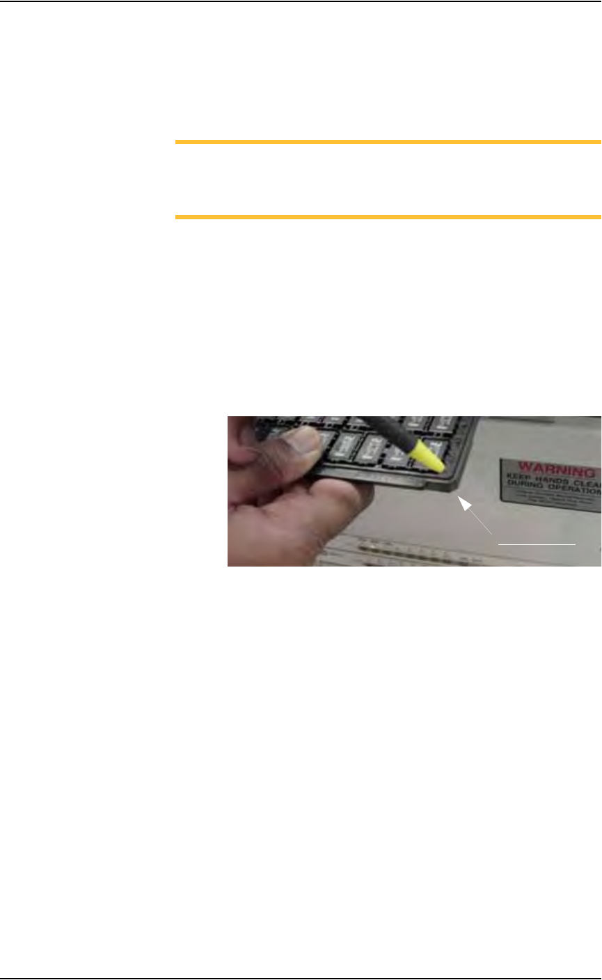
2a) Orient the static trays so that the beveled edge is in the lower right cor-
ner. See Figure 2-4.
Figure 2-4—Static tray orientation
2b) Slip trays into Static Tray 1 and Static Tray 2 locations.
2c) Place the “L” shaped magnet in the upper right corner of each tray so
that the each tray seats against the 4 positioning pins. When properly
seated, each tray blocks an optic sensor. See Figure 2-5.
Beveled edge