PS288_OwnersMnl_PriorTo2009 - 第40页
Set Up • Setting Up Static Tray Input/Out put 2—6 PS288 Owner’s Manual Figur e 2-5—T wo S tatic T rays seated with optic sensors (hidden) blocked CAUTION: If a Job is Paused and a static t ray is removed fr om the S tati…
Set Up • Setting Up Static Tray Input/Output
PS288 Owner’s Manual 2—5
If electrical or mechanical problems are noted, turn off the PS288 and notify
Data I/O Customer Support immediately.
Setting Up
Static Tray
Input/Output
Static tray input and output is the standard configuration on the PS288.
NOTE: When using static tray input and output, ensure that blank
devices are loaded with the correct pin 1 orientation. Pin 1 orienta-
tion is set when the PNP head locations are taught. For more infor-
mation, see “Teach Tray Locations” on page 3-38.
To set up the static tray input and output:
1. Prepare system—
1a) If a job is running, press Pause on the Run window.
1b) Press Exit to return to the Setup window.
1c) Click the Options tab.
1d) Open the front safety shield.
2. Install Static Trays—
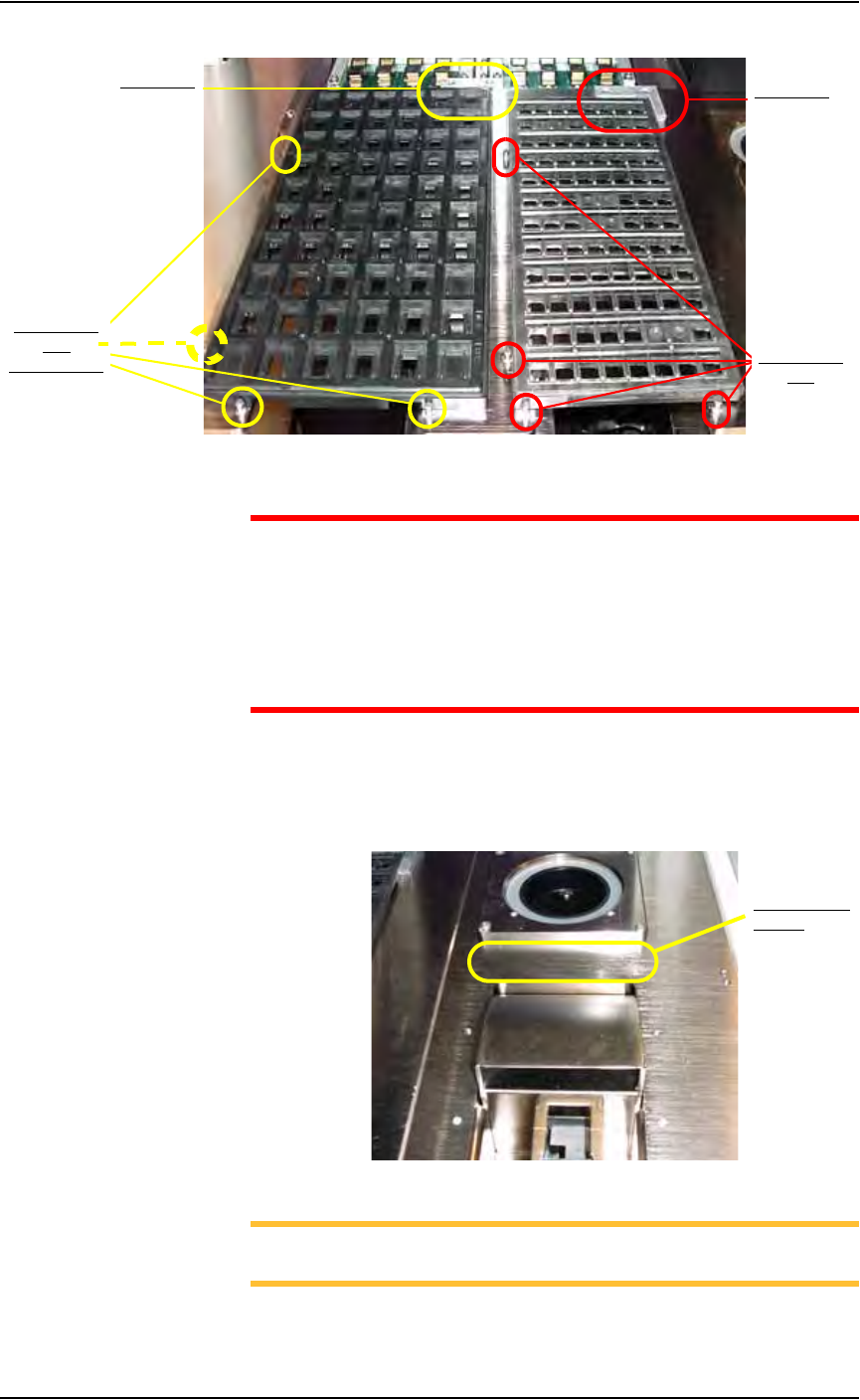
2a) Orient the static trays so that the beveled edge is in the lower right cor-
ner. See Figure 2-4.
Figure 2-4—Static tray orientation
2b) Slip trays into Static Tray 1 and Static Tray 2 locations.
2c) Place the “L” shaped magnet in the upper right corner of each tray so
that the each tray seats against the 4 positioning pins. When properly
seated, each tray blocks an optic sensor. See Figure 2-5.
Beveled edge
Set Up • Setting Up Static Tray Input/Output
2—6 PS288 Owner’s Manual
Figure 2-5—Two Static Trays seated with optic sensors (hidden) blocked
CAUTION: If a Job is Paused and a static tray is removed from the
Static Tray 1 or Static Tray 2 location and then returned to the
Static Tray 1 or Static Tray 2 location, the software detects that the
optic sensor was uncovered. As a result, all devices in a static tray
are reset to new, and the PS288 proceeds as if all devices are blank
(unprogrammed). Therefore, use caution when removing partially
programmed static trays.
3. Install optional reject bin/box—
Place a small bin or box to the front of the Vision position (and behind
the optional Tape input position) on the work surface, as shown in Fig-
ure 2-6.
Figure 2-6—Reject bin/box location
NOTE: On the Gantry window, the reject bin/box is represented
with the RTr yellow position label.
4 Positioning
Pins
4 Positioning
Pins
(one pin hidden)
“L” bracket
“L” bracket
Reject bin/box
location
Set Up • (Optional) Setting Up the Automatic Tray Feeder
PS288 Owner’s Manual 2—7
This completes the procedure for setting up of the static tray input and output
module.
Before running a job for the first time, it is necessary to:
• Select tray input/output settings in the AH500 software. For informa-
tion, see “Configure Input/Output Settings” on page 3-4.
• Teach locations to the PNP head. For information, see “Teach the Pack-
age File” on page 3-33.
(Optional)
Setting Up the
Automatic Tray
Feeder
The PS288 can be configured with either the TF20 or TF30 automatic tray
feeder.
For automatic tray feeder setup, see the installation instructions supplied
with the TF20 or TF30.
For information on operating the TF20, see “(Optional) Operate the TF20
Automatic Tray Feeder” on page 3-18.
For information on operating the TF30, see “(Optional) Operate the TF30
Automatic Tray Feeder” on page 3-19.
(Optional)
Setting Up the
Tube Input and
Tube Output
Modules
As an option, the PS288 can be configured with tube input and tube output
modules.
To set up the tube input and output modules:
1. Collect materials—
1a) Determine the size of the devices to be programmed and select tubes
that match device size.
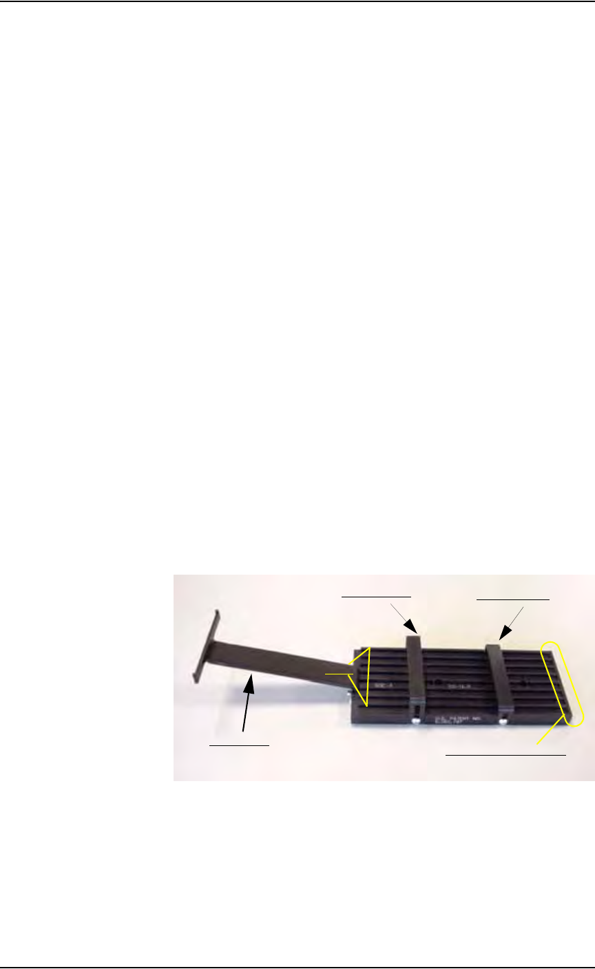
1b) Identify the input tube loader platform. See Figure 2-7.
Figure 2-7—Input tube loader platform
2. Install input tube loader platform—
2a) Open the front safety shield.
2b) Install the input tube loader platform onto the input Vibrator Motor 1
(V1) on the left side of the work surface. Vibrator Motor 1 is shown in
Figure 2-8.
2c) Tighten the two screws using a 9/64 inch Allen wrench.
Rear tube guide
Front tube guide
Tube elevator
Lanes
Pick location (staging area)