PS288_OwnersMnl_PriorTo2009 - 第42页
Set Up • (Optional) Setting Up the Tube Input and Tube Out put Modules 2—8 PS288 Owner’s Manual Figur e 2-8—V1 and V2 3. Install output tube unloader platform— 3a) Install the output tube unloader plat form onto the outp…
Set Up • (Optional) Setting Up the Automatic Tray Feeder
PS288 Owner’s Manual 2—7
This completes the procedure for setting up of the static tray input and output
module.
Before running a job for the first time, it is necessary to:
• Select tray input/output settings in the AH500 software. For informa-
tion, see “Configure Input/Output Settings” on page 3-4.
• Teach locations to the PNP head. For information, see “Teach the Pack-
age File” on page 3-33.
(Optional)
Setting Up the
Automatic Tray
Feeder
The PS288 can be configured with either the TF20 or TF30 automatic tray
feeder.
For automatic tray feeder setup, see the installation instructions supplied
with the TF20 or TF30.
For information on operating the TF20, see “(Optional) Operate the TF20
Automatic Tray Feeder” on page 3-18.
For information on operating the TF30, see “(Optional) Operate the TF30
Automatic Tray Feeder” on page 3-19.
(Optional)
Setting Up the
Tube Input and
Tube Output
Modules
As an option, the PS288 can be configured with tube input and tube output
modules.
To set up the tube input and output modules:
1. Collect materials—
1a) Determine the size of the devices to be programmed and select tubes
that match device size.
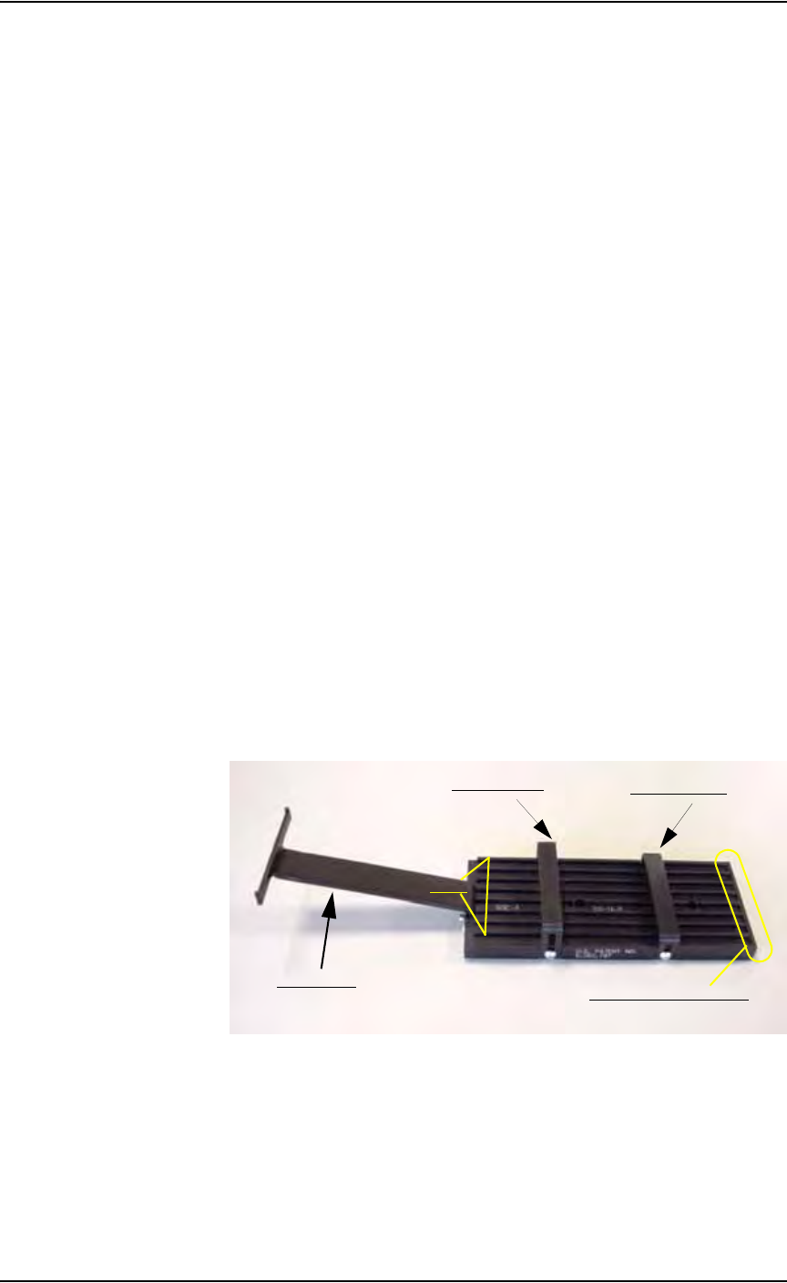
1b) Identify the input tube loader platform. See Figure 2-7.
Figure 2-7—Input tube loader platform
2. Install input tube loader platform—
2a) Open the front safety shield.
2b) Install the input tube loader platform onto the input Vibrator Motor 1
(V1) on the left side of the work surface. Vibrator Motor 1 is shown in
Figure 2-8.
2c) Tighten the two screws using a 9/64 inch Allen wrench.
Rear tube guide
Front tube guide
Tube elevator
Lanes
Pick location (staging area)
Set Up • (Optional) Setting Up the Tube Input and Tube Output Modules
2—8 PS288 Owner’s Manual
Figure 2-8—V1 and V2
3. Install output tube unloader platform—
3a) Install the output tube unloader platform onto the output Vibrator
Motor 2 (V2) on the right side of the work surface. Vibrator Motor 2 is
shown in Figure 2-8 above.
3b) Tighten the two screws using a 9/64 inch Allen wrench.
4. Insert tubes in input tube platform—
4a) Insert empty tubes in the first and last lanes of the input tube loader
platform. See Figure 2-9.
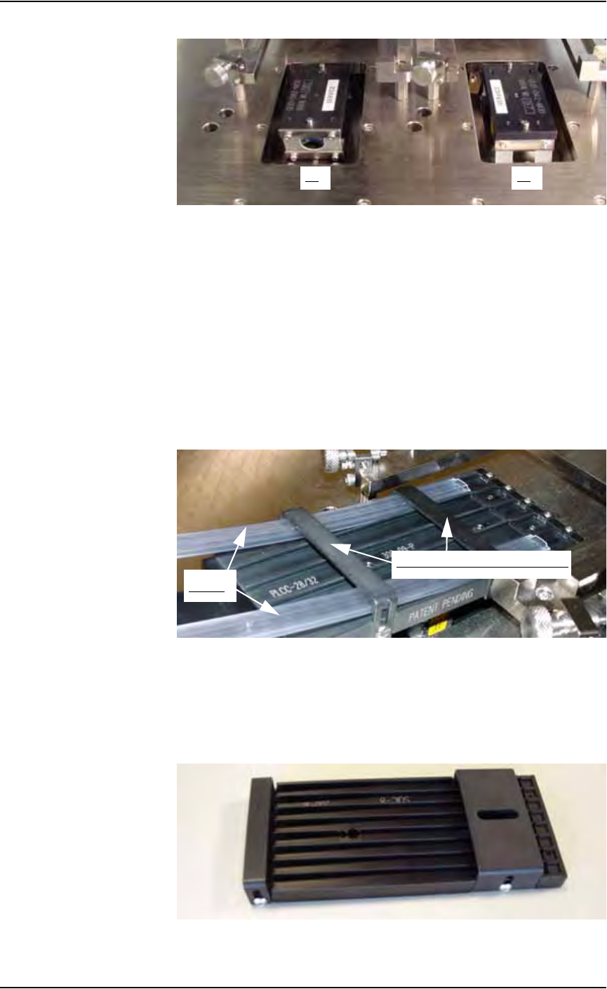
4b) Adjust the rear tube guide and the front tube guide so the tubes are held
on the input tube platform snugly but are not compressed out of shape.
See Figure 2-9.
Figure 2-9—Adjust front and rear tube guides
4c) Remove the empty tubes from the first and last lanes of the input tube
loader platform.
5. Adjust output tube unloader platform—
5a) Identify the output tube unloader platform. See Figure 2-10.
Figure 2-10—Output tube unloader platform
V1 V2
Front and Rear Tube Guides
Tubes

Set Up • (Optional) Setting Up the Tube Input and Tube Output Modules
PS288 Owner’s Manual 2—9
5b) Adjust the output tube unloader platform front and rear tube guides as
described in Step 4 above.
6. Insert tubes—
6a) Insert full tubes into the input tube loader platform.
6b) Insert empty tubes into the output tube unloader platform.
6c) Close the safety shield.
NOTE: The pin 1 orientation for devices is set in the package file.
Devices should be loaded in tubes as defined in the package file.
NOTE: If this is the first time you are installing tube feeders on
your PS288, you may need to edit the WinAH400.ini file to reflect
this additional option. Proceed with Step 7.
If you have previously installed tube feeders on your PS288, skip to
Step 8.
7. Configuring AH500 after first tube feeder installation—
7a) Make a backup copy of WinAH400.ini: e.g., WinAH400backup.ini.
7b) Using Windows Explorer, open C:\AH400_32\WinAH400.ini.with
NOTEPAD editor.
7c) Locate the section
;------- tube media settings -----
7d) Ensure that the value for Tube Feeder 1 (input tube feeder) is
STDIN. Change if it is not.
7e) Ensure that the value for Tube Feeder 2 (output tube feeder) is
STDOUT. Change if it is not.
7f) Save the WinAH400.ini file and exit Windows Explorer.
8. Configuring AH500 after repeat tube feeder installation—
8a) On the Options window, select "Tubes" for the input and output media.
8b) If the vision system will be used to check every device, set Vision Sys-
tem to ON.
8c) If the vision system will be used to check only the first and last devices
in a tube, set Vision System to OFF and check “1st +last 2 /tube.”
9. Adjust vibration controls—
If devices do not travel freely in the input tubes or the output tubes,
increase the vibration by turning the vibration controls clockwise. The
magnitude of vibration is set by adjusting V1 for the input tubes and
V2 for the output tubes.
NOTE: Within AH500’s Gantry window, Vibrator 1 is represented
by the yellow position label Vib1. Vibrator 2 is represented by the
yellow position label Vib2.
This completes the procedure for setting up a tube input and tube output
modules.