PS288_OwnersMnl_PriorTo2009 - 第45页
Set Up • (Optional) Setting Up the Tape Input Feeder PS288 Owner’s Manual 2—11 Figur e 2-12—Main window 2b) Remove the two screws holding the small safety shield th at covers the tape input feeder slot. Figur e 2-13—Remo…
Set Up • (Optional) Setting Up the Tape Input Feeder
2—10 PS288 Owner’s Manual
Before running a job for the first time, it is necessary to:
• Teach locations to the PNP head. For information, see “Teach the Pack-
age File” on page 3-33.
(Optional)
Setting Up the
Tape Input
Feeder
The PS288 can be configured with an optional tape input feeder. The tape
input feeder is installed on the front of the PS288.
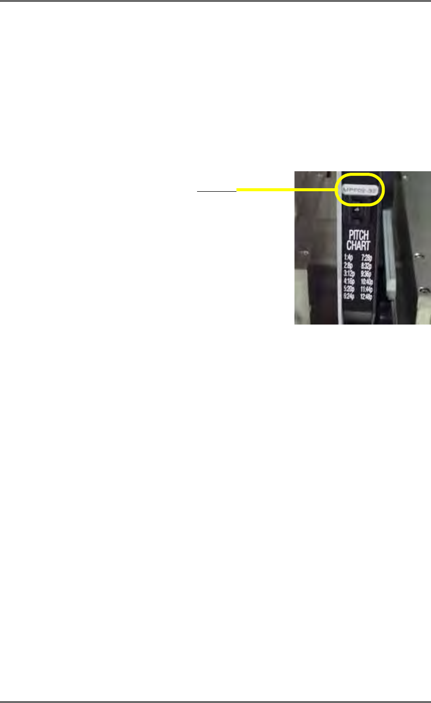
Tape input feeders are available in 8, 12, 16, 24, 32, 44, and 56 mm sizes to
match device tape of those widths. The last two digits of the tape input
feeder part number indicate the tape width. For example, a 32 mm tape input
feeder has a part number ending in 32. See Figure 2-11.
Figure 2-11—Part number for 32 mm feeder
To install the tape input feeder:
1. For first-time installation—
If the tape input feeder is being installed for the first time on your
PS288, the WinAH400.ini file may need to be edited to reflect this
additional option.
1a) Using Windows Explorer, open C:\AH400_32\WinAH400.ini with
NOTEPAD editor.
1b) Locate the section
;------- tape input/output -----
1c) Ensure value for Tape Advance Installed is TRUE, as shown.
TapeAdvanceInstalled=TRUE
1d) Save the WinAH400.ini file and exit Windows Explorer.
2. Prepare the system—
2a) From the Handler Computer interface, stop any Job that is running and
exit to the main window as shown in Figure 2-12.
Part number

Set Up • (Optional) Setting Up the Tape Input Feeder
PS288 Owner’s Manual 2—11
Figure 2-12—Main window
2b) Remove the two screws holding the small safety shield that covers the
tape input feeder slot.
Figure 2-13—Remove two screws holding small safety shield
2c) Remove the small safety shield and set it aside. It is not used when the
tape input feeder unit is installed.
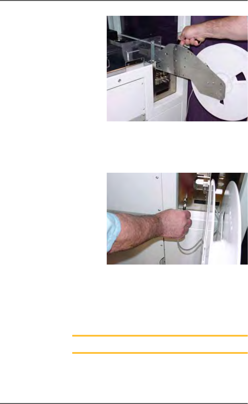
3. Mount the feeder unit—
3a) Align the rail on the bottom of the feeder unit with the channel in the
base plate.
3b) Slide the feeder unit down the channel until the feeder unit reaches the
front wedge. See Figure 2-14.
Set Up • (Optional) Setting Up the Tape Input Feeder
2—12 PS288 Owner’s Manual
Figure 2-14— Slide feeder unit down channel
3c) Push the feeder down.
4. Connect interface cable—
Insert interface cable into the plug and push until cable snaps in. See
Figure 2-15.
Figure 2-15—Connect interface cable
5. Mount device reel—
5a) Orient the reel so that devices are on the top of the carrier tape as the
tape comes off the reel.
5b) Slide the reel onto the reel pin shaft and lock on the locating ridge.
5c) Rotate the reel pin cap to secure the reel to the shaft.
6. Thread device carrier tape—
NOTE: For more information about threading device carrier tape,
see the manual that came with your tape feeder system.
6a) Insert device carrier tape under the input roller.
6b) Thread device carrier tape down the input guide so that it sits under the
guide and on top of the step.