PS288_OwnersMnl_PriorTo2009 - 第46页
Set Up • (Optional) Setting Up the Tape Input Feeder 2—12 PS288 Owner’s Manual Figur e 2-14— Slide feeder unit down channel 3c) Push the feeder down. 4. Connect interface cable— Insert interface cable into the plug and p…
Set Up • (Optional) Setting Up the Tape Input Feeder
PS288 Owner’s Manual 2—11
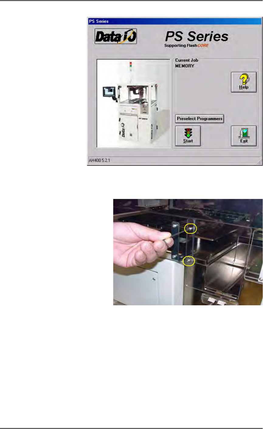
Figure 2-12—Main window
2b) Remove the two screws holding the small safety shield that covers the
tape input feeder slot.
Figure 2-13—Remove two screws holding small safety shield
2c) Remove the small safety shield and set it aside. It is not used when the
tape input feeder unit is installed.
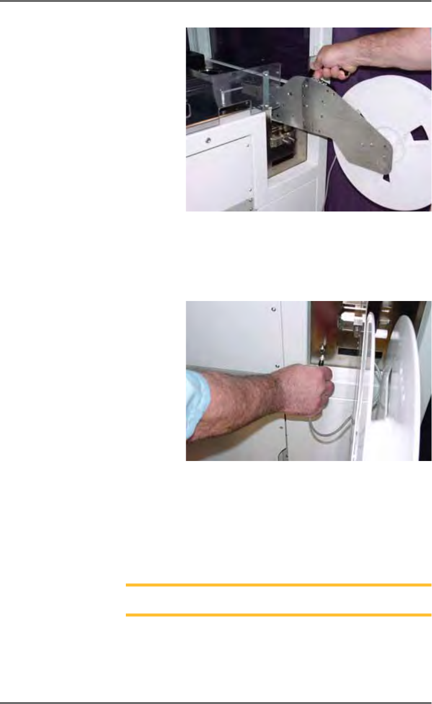
3. Mount the feeder unit—
3a) Align the rail on the bottom of the feeder unit with the channel in the
base plate.
3b) Slide the feeder unit down the channel until the feeder unit reaches the
front wedge. See Figure 2-14.
Set Up • (Optional) Setting Up the Tape Input Feeder
2—12 PS288 Owner’s Manual
Figure 2-14— Slide feeder unit down channel
3c) Push the feeder down.
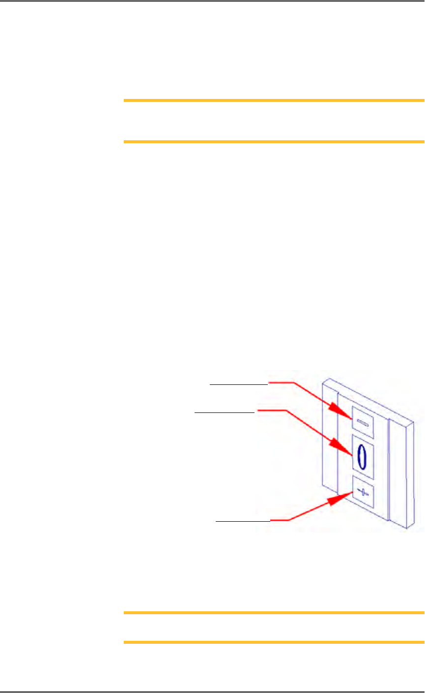
4. Connect interface cable—
Insert interface cable into the plug and push until cable snaps in. See
Figure 2-15.
Figure 2-15—Connect interface cable
5. Mount device reel—
5a) Orient the reel so that devices are on the top of the carrier tape as the
tape comes off the reel.
5b) Slide the reel onto the reel pin shaft and lock on the locating ridge.
5c) Rotate the reel pin cap to secure the reel to the shaft.
6. Thread device carrier tape—
NOTE: For more information about threading device carrier tape,
see the manual that came with your tape feeder system.
6a) Insert device carrier tape under the input roller.
6b) Thread device carrier tape down the input guide so that it sits under the
guide and on top of the step.
Set Up • (Optional) Setting Up the Tape Input Feeder
PS288 Owner’s Manual 2—13
6c) Thread device carrier tape under cover tape roller.
6d) Lift the spring-loaded tape window latch and lift the tape window.
6e) Pull device carrier tape until it is visible at the end of the feeder unit.
6f) Separate cover tape from the device carrier tape.
6g) Pull device carrier tape forward to feed into carrier waste tape channel.
NOTE: The empty device carrier tape will eventually come out of
the channel. Place a reject box on the floor to contain empty device
carrier tape.
6h) Align the guide holes in the device carrier tape with the teeth on the
Drive Sprocket.
7. Thread cover tape—
7a) Thread the cover tape through the tape window, under the window
roller, and over the cover tape roller.
7b) Thread the cover tape under the cover tape wheel.
7c) Attach the end of the cover tape to the cover tape wheel using a small
piece of adhesive tape.
8. Adjust pitch—
8a) Count the number of guide holes in the carrier tape between the center
of one pocket and the center of the next pocket.
8b) On the feeder unit control panel, set the pitch index to the number of
guide holes. For example, if there are 4 guide holes from center to cen-
ter, enter 4 in the pitch index. Use the - and + buttons to lower or raise
the pitch index. See Figure 2-16.
Figure 2-16—Setting pitch index
9. Switch on the feeder unit—
9a) Close all safety shields and release E-Stop buttons.
9b) On the Gantry window, press Park.
NOTE: The circuit breaker K1 is now engaged and power is on for
the feeder unit.
Lower pitch index
Raise pitch index
Pitch index display