PS288_OwnersMnl_PriorTo2009 - 第48页
Set Up • (Optional) Setting Up the Tape Output System 2—14 PS288 Owner’s Manual 10. Align pick point— 10a) On the feeder unit control panel, press and hold the center button. 10b) While holding the center button, p ress …
Set Up • (Optional) Setting Up the Tape Input Feeder
PS288 Owner’s Manual 2—13
6c) Thread device carrier tape under cover tape roller.
6d) Lift the spring-loaded tape window latch and lift the tape window.
6e) Pull device carrier tape until it is visible at the end of the feeder unit.
6f) Separate cover tape from the device carrier tape.
6g) Pull device carrier tape forward to feed into carrier waste tape channel.
NOTE: The empty device carrier tape will eventually come out of
the channel. Place a reject box on the floor to contain empty device
carrier tape.
6h) Align the guide holes in the device carrier tape with the teeth on the
Drive Sprocket.
7. Thread cover tape—
7a) Thread the cover tape through the tape window, under the window
roller, and over the cover tape roller.
7b) Thread the cover tape under the cover tape wheel.
7c) Attach the end of the cover tape to the cover tape wheel using a small
piece of adhesive tape.
8. Adjust pitch—
8a) Count the number of guide holes in the carrier tape between the center
of one pocket and the center of the next pocket.
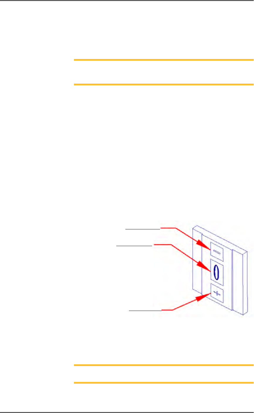
8b) On the feeder unit control panel, set the pitch index to the number of
guide holes. For example, if there are 4 guide holes from center to cen-
ter, enter 4 in the pitch index. Use the - and + buttons to lower or raise
the pitch index. See Figure 2-16.
Figure 2-16—Setting pitch index
9. Switch on the feeder unit—
9a) Close all safety shields and release E-Stop buttons.
9b) On the Gantry window, press Park.
NOTE: The circuit breaker K1 is now engaged and power is on for
the feeder unit.
Lower pitch index
Raise pitch index
Pitch index display
Set Up • (Optional) Setting Up the Tape Output System
2—14 PS288 Owner’s Manual
10. Align pick point—
10a) On the feeder unit control panel, press and hold the center button.
10b) While holding the center button, press the forward button. The carrier
tape advances one guide hole. Advance the carrier tape in this manner
until the pick point mark on the tape window aligns with the center of
the pocket.
10c) Release the center button. Press the forward button once to index the
device tape forward one pocket.
11. Replace full cover tape reel—
11a) Remove full cover tape reel from spindle.
11b) Pull off cover tape.
11c) Replace cover tape reel.
This completes the procedure for setting up the tape input feeder.
Before running a job with the tape input feeder in place, it is necessary to:
• Teach locations to the PNP head. For information, see “Teach the Pack-
age File” on page 3-33.
• Select tape input setting in the AH500 software. For information, see
“Configure Input/Output Settings” on page 3-4.
(Optional)
Setting Up the
Tape Output
System
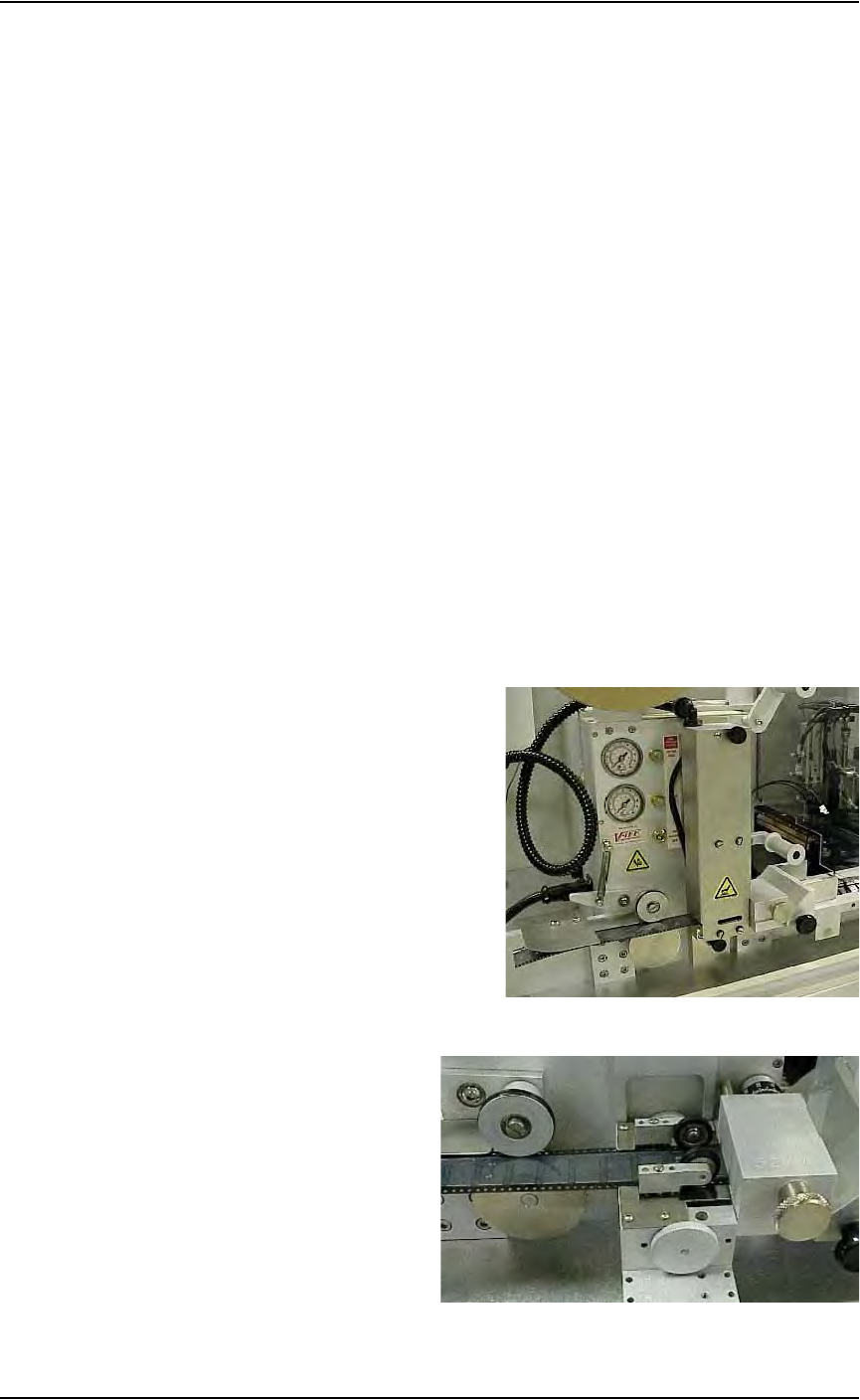
The PS288 can be configured with an optional tape output system attached
to the Option Bay. Tape output systems come with either heat seal or pres-
sure seal units. See Figure 2-17 and Figure 2-18 below:
Figure 2-17—Heat seal unit
Figure 2-18—Pressure seal unit

Set Up • (Optional) Setting Up the Tape Output System
PS288 Owner’s Manual 2—15
NOTE: Installation of the tape output system is the same for both
pressure seal and heat seal units, unless noted otherwise. Refer to
the manual that came with your heat seal unit (Taping Machine
Operator’s Manual) or pressure seal unit (Universal PSA Sealer
Operator’s Manual) for additional information.
To set up the tape output system:
1. For first-time installation—
If the tape output system is being installed for the first time, the
WinAH400.ini file may need to be edited to reflect this additional
option.
1a) Using Windows Explorer, open C:\AH400_32\WinAH400.ini.with
NOTEPAD editor.
1b) Locate the section
;------- tape input/output -----
1c) Ensure value for Tape Output Installed is TRUE, as shown.
TapeOutputInstalled=TRUE
1d) Save the WinAH400.ini file and exit Windows Explorer.
2. Determine the width of the carrier tape—
Standard sizes are 8, 12, 16, 24, 32, 44, and 56mm.
3. Install carrier tape supply reel—
Place the reel on the spindle so that the carrier tape comes off the top of
the reel with the empty carrier pockets facing up.
4. Insert tape into feeder—
4a) Thread the end of the carrier tape under the Front Tape Guide.
4b) Thread the tape into the Adjustable Loading Track so that it sits under
the guide and on top of the channel, as shown in Figure 2-19.
Figure 2-19—Carrier tape threaded into track
5. Adjust width of Adjustable Loading Track—
The Adjustable Loading Track has detents at 8, 12, 16, 24, 32, 44, and
56 mm widths. Adjust the width of the Adjustable Loading Track by
gently pushing in or pulling out the near side to match the width of the
carrier tape, as shown in Figure 2-20.