PS288_OwnersMnl_PriorTo2009 - 第50页
Set Up • (Optional) Setting Up the Tape Output System 2—16 PS288 Owner’s Manual Figur e 2-20—Adjustable Loading T rack 6. Advance carrier tape— Slide the carrier tape to the left until it passes the Out of Pocket sensor,…
Set Up • (Optional) Setting Up the Tape Output System
PS288 Owner’s Manual 2—15
NOTE: Installation of the tape output system is the same for both
pressure seal and heat seal units, unless noted otherwise. Refer to
the manual that came with your heat seal unit (Taping Machine
Operator’s Manual) or pressure seal unit (Universal PSA Sealer
Operator’s Manual) for additional information.
To set up the tape output system:
1. For first-time installation—
If the tape output system is being installed for the first time, the
WinAH400.ini file may need to be edited to reflect this additional
option.
1a) Using Windows Explorer, open C:\AH400_32\WinAH400.ini.with
NOTEPAD editor.
1b) Locate the section
;------- tape input/output -----
1c) Ensure value for Tape Output Installed is TRUE, as shown.
TapeOutputInstalled=TRUE
1d) Save the WinAH400.ini file and exit Windows Explorer.
2. Determine the width of the carrier tape—
Standard sizes are 8, 12, 16, 24, 32, 44, and 56mm.
3. Install carrier tape supply reel—
Place the reel on the spindle so that the carrier tape comes off the top of
the reel with the empty carrier pockets facing up.
4. Insert tape into feeder—
4a) Thread the end of the carrier tape under the Front Tape Guide.
4b) Thread the tape into the Adjustable Loading Track so that it sits under
the guide and on top of the channel, as shown in Figure 2-19.
Figure 2-19—Carrier tape threaded into track
5. Adjust width of Adjustable Loading Track—
The Adjustable Loading Track has detents at 8, 12, 16, 24, 32, 44, and
56 mm widths. Adjust the width of the Adjustable Loading Track by
gently pushing in or pulling out the near side to match the width of the
carrier tape, as shown in Figure 2-20.
Set Up • (Optional) Setting Up the Tape Output System
2—16 PS288 Owner’s Manual
Figure 2-20—Adjustable Loading Track
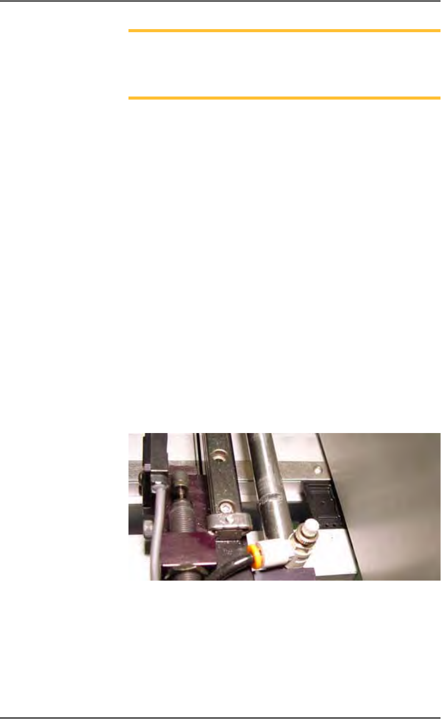
6. Advance carrier tape—
Slide the carrier tape to the left until it passes the Out of Pocket sensor,
as shown in Figure 2-21.
Figure 2-21—Out of Pocket sensor and tape location on the tape output
7. Install seal unit—
HEAT SEAL UNIT:
• Install the heat seal unit that matches the width of the carrier tape. Heat
seal units come in 8, 12, 16, 24, 32, 44, and 56 mm sizes.
• Use the long screw to attach the heat seal unit at the top and the short
screw to attach it at the bottom. See Figure 2-22.
Figure 2-22—Installing heat seal unit
End of carrier tape
Out of Pocket sensor
Set Up • (Optional) Setting Up the Tape Output System
PS288 Owner’s Manual 2—17
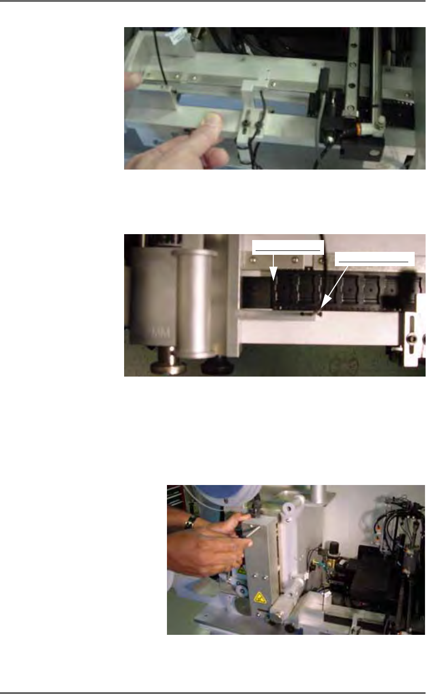
PRESSURE SEAL UNIT:
• Remove the Allen head screw on top of pressure seal unit.
• Adjust the width of pressure seal unit to match the width of tape.
• Tighten the Allen head screw. See Figure 2-23.
Figure 2-23—Adjusting width of pressure seal unit
• Use the short screw to attach the pressure seal unit at the top and the
long screw to attach it at the bottom. See Figure 2-24.
Figure 2-24—Installing pressure seal unit
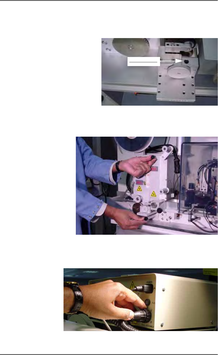
8. Plug seal unit into control box—
Insert the power cord from the seal unit into the tape output controller
as shown in Figure 2-25.
Figure 2-25—Power cord in tape output controller
Allen head screw