PS288_OwnersMnl_PriorTo2009 - 第52页
Set Up • (Optional) Setting Up the Tape Output System 2—18 PS288 Owner’s Manual 9. Switch on and adjust seal pressure— 9a) T urn the Air Pressure ON/OFF Switch to ON . 9b) Set the Seal Pressure Ad just Controls so that I…
Set Up • (Optional) Setting Up the Tape Output System
PS288 Owner’s Manual 2—17
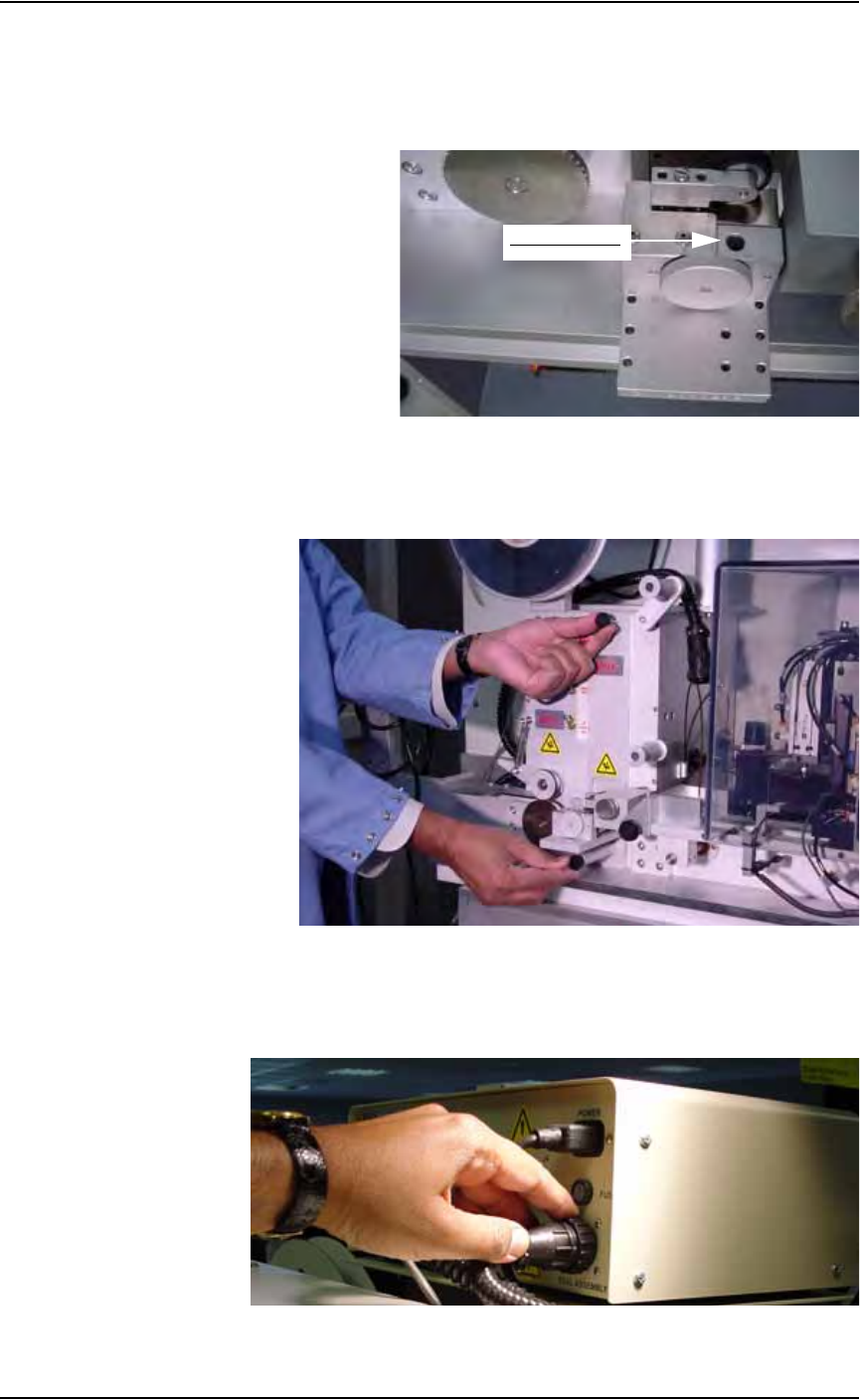
PRESSURE SEAL UNIT:
• Remove the Allen head screw on top of pressure seal unit.
• Adjust the width of pressure seal unit to match the width of tape.
• Tighten the Allen head screw. See Figure 2-23.
Figure 2-23—Adjusting width of pressure seal unit
• Use the short screw to attach the pressure seal unit at the top and the
long screw to attach it at the bottom. See Figure 2-24.
Figure 2-24—Installing pressure seal unit
8. Plug seal unit into control box—
Insert the power cord from the seal unit into the tape output controller
as shown in Figure 2-25.
Figure 2-25—Power cord in tape output controller
Allen head screw
Set Up • (Optional) Setting Up the Tape Output System
2—18 PS288 Owner’s Manual
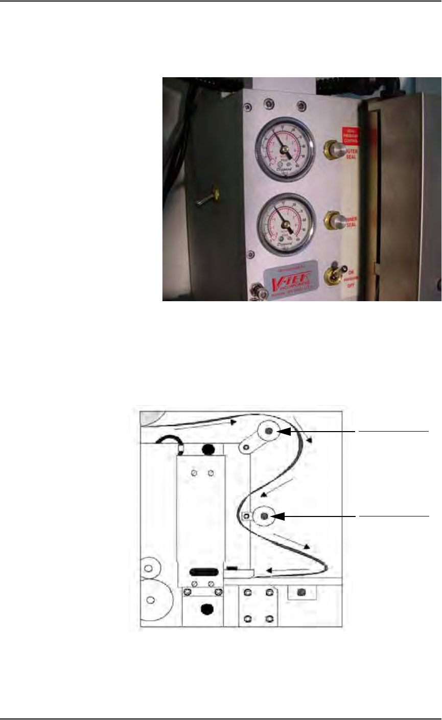
9. Switch on and adjust seal pressure—
9a) Turn the Air Pressure ON/OFF Switch to ON.
9b) Set the Seal Pressure Adjust Controls so that Inner and Outer air pres-
sure are 40-50 PSI, as shown in Figure 2-26.
Figure 2-26—Seal pressure control settings
10. Install cover tape—
10a) Select cover tape of the same width as the carrier tape.
10b) Install the cover tape reel on the spindle so that the smooth side of the
cover tape faces the seal unit.
10c) Thread the cover tape around Cover Tape Guide #1 and Cover Tape
Guide #2 as shown in Figure 2-27.
Figure 2-27—Path of cover tape
11. Turn power on to tape output controller—
11a) Set Seal Switch to ON position.
Cover Tape Guide #1
Cover Tape Guide #2
Set Up • (Optional) Setting Up the Tape Output System
PS288 Owner’s Manual 2—19
11b) Set Inside and Outside temperature to 150-160
° C.
11c) Wait for temperature to reach target range. See Figure 2-28.
Figure 2-28—Power and heat settings
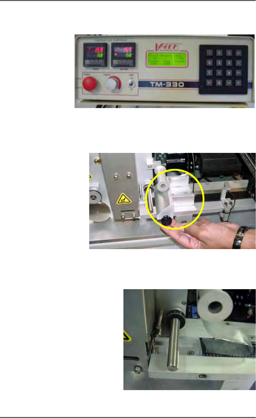
12. Remove Sensor Clamp Block—
Remove and set aside the Sensor Clamp Block to facilitate advancing
the carrier tape through the seal unit. See Figure 2-29.
Figure 2-29—Remove sensor clamp block
13. Attach cover tape to carrier tape—
Use a small piece of adhesive tape to attach the end of the cover tape to
the carrier tape. See Figure 2-30.
Figure 2-30—Combine cover and carrier tape