PS288_OwnersMnl_PriorTo2009 - 第54页
Set Up • (Optional) Setting Up the Tape Output System 2—20 PS288 Owner’s Manual 14. Advance combined tape— Advance the combined cover/ carrier tape through the seal unit. 15. Install Cover T ape Guide #3— 15a) Cover T ap…
Set Up • (Optional) Setting Up the Tape Output System
PS288 Owner’s Manual 2—19
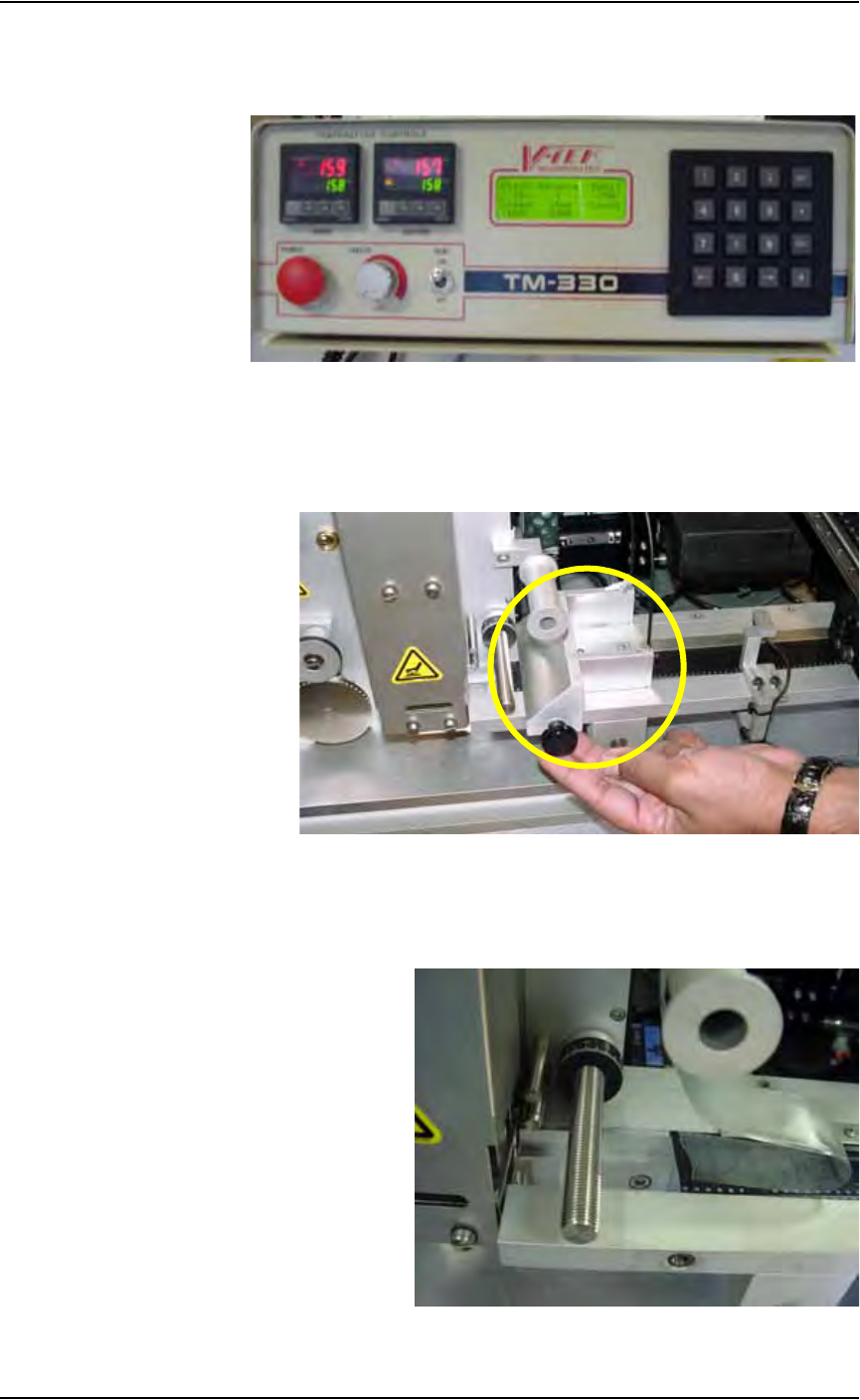
11b) Set Inside and Outside temperature to 150-160
° C.
11c) Wait for temperature to reach target range. See Figure 2-28.
Figure 2-28—Power and heat settings
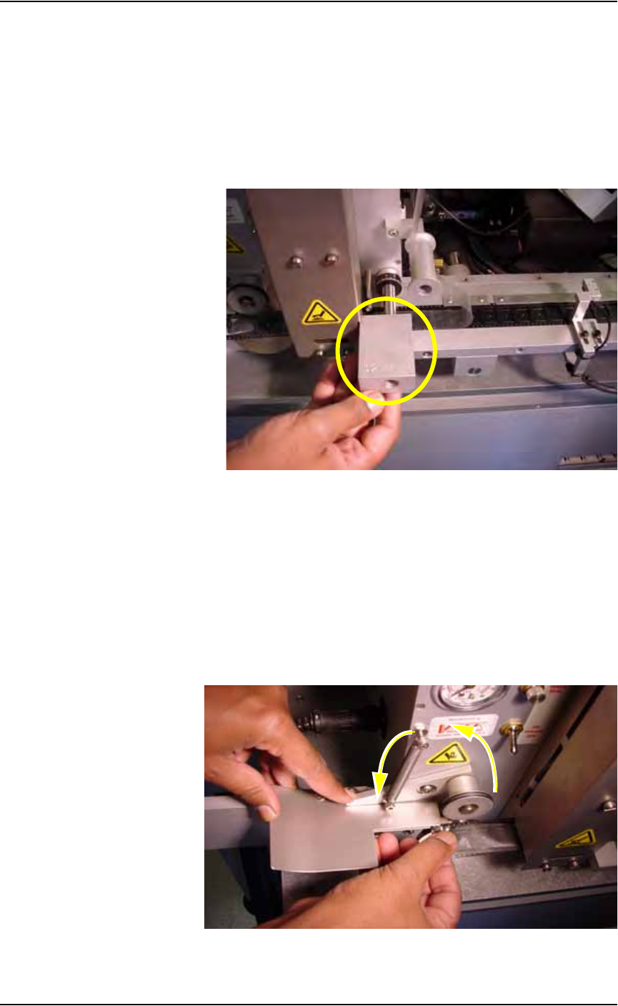
12. Remove Sensor Clamp Block—
Remove and set aside the Sensor Clamp Block to facilitate advancing
the carrier tape through the seal unit. See Figure 2-29.
Figure 2-29—Remove sensor clamp block
13. Attach cover tape to carrier tape—
Use a small piece of adhesive tape to attach the end of the cover tape to
the carrier tape. See Figure 2-30.
Figure 2-30—Combine cover and carrier tape
Set Up • (Optional) Setting Up the Tape Output System
2—20 PS288 Owner’s Manual
14. Advance combined tape—
Advance the combined cover/carrier tape through the seal unit.
15. Install Cover Tape Guide #3—
15a) Cover Tape Guide #3 comes in 8, 12, 16, 24, 32, 44, and 56 mm sizes.
Pick the size that matches the carrier tape width.
15b) Slide Cover Tape Guide #3 onto shaft (as shown in Figure 2-31) and
tighten the knurled knob.
Figure 2-31—Cover Tape Guide #3
15c) Reinstall the Sensor Clamp Block.
16. Advance combined cover/carrier tape through seal unit—
Slide the combined cover/carrier tape through the seal unit until it is
visible on the left of the seal unit.
17. Drive sprocket—
17a) Lift the Idler Arm and insert the combined cover/carrier tape.
17b) Align the holes on the combined cover/carrier tape with the teeth on the
Drive Sprocket. See Figure 2-32.
Figure 2-32—Idler Arm and Drive Sprocket
Set Up • (Optional) Setting Up the Tape Output System
PS288 Owner’s Manual 2—21
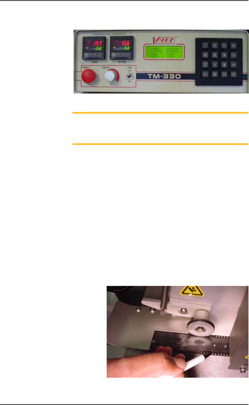
18. Set tape output controller values—
18a) On the tape output controller, press ESC to display the main menu.
Figure 2-33—Tape output controller main menu
NOTE: Values used in this example are for illustration purposes
only. For more specific information, refer to "Approximate Starting
Points for Seal Controls" on page 16 of 36 in the TM-330 Taping
Machine Operator’s Manual that came with your system.
18b) Select 2 for Pitch. Count the number of guide holes in the carrier tape
between the center of one pocket and the center of the next pocket.
Enter that number for the Pitch value.
18c) Select 4 for Speed. Enter 100 and press ENT.
18d) Select 7 for Mode. On the Mode window, select choice 2. An asterisk
(*) appears to the right of “Heat Seal w/32mm.” Press ESC.
18e) Select 5 for Dwell. Verify the value is 350-400. Press ENT.
18f) Select 3 for Advance. On the Advance window, Select 1. Press ENT.
18g) Select 8 for Run. Verify values.
19. Advance the combined cover/carrier tape—
Step on the foot pedal to advance the combined cover/carrier tape
100-125 millimeters (4-5 inches) to the left of the seal unit.
20. Inspect position of cover tape over carrier tape—
The cover tape should align over the carrier tape so that the cover tape
touches the side rails of the carrier tape and but does not cover the
guide holes on the carrier tape. See Figure 2-34.
Figure 2-34—Alignment of cover tape over carrier tape