PS288_OwnersMnl_PriorTo2009 - 第57页
Set Up • (Optional) Setting Up the Tape Output System PS288 Owner’s Manual 2—23 23a) On the PLC controller: • T oggle DOWN the switch labeled “Transfer .” • T oggle DOWN the switch labeled “Long Stroke.” • T oggle DOWN t…
Set Up • (Optional) Setting Up the Tape Output System
2—22 PS288 Owner’s Manual
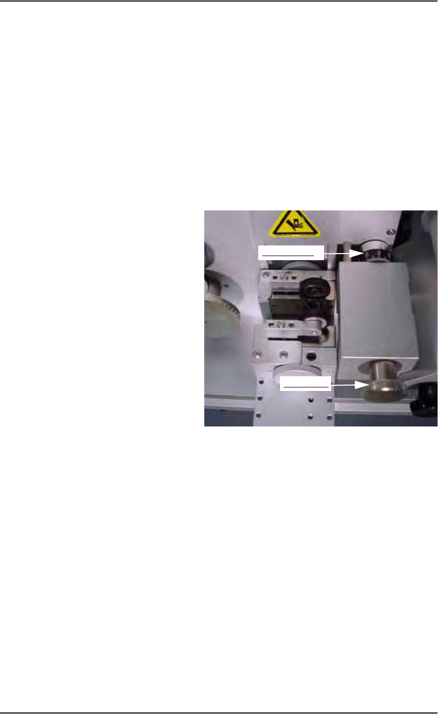
If the cover tape does not align properly, adjust Cover Tape Guide #3 as
follows (refer to Figure 2-35).
• If cover tape needs to move toward the outside of the carrier tape,
loosen the knurled knob on Cover Tape Guide #3 and turn the adjust-
ment dial counterclockwise. Tighten the knurled knob on Cover Tape
Guide #3 and advance the tape 10-13 cm to the left of the seal unit.
Recheck the alignment of cover tape over carrier tape. Repeat until
cover tape centers on carrier tape.
• If cover tape needs to move toward the inside of the carrier tape, loosen
the knurled knob on Cover Tape Guide #3 and turn the adjustment dial
clockwise. Tighten the knurled knob on Cover Tape Guide #3 and
advance the tape 10-13 cm to the left of the seal unit. Recheck the
alignment of cover tape over carrier tape. Repeat until cover tape cen-
ters on carrier tape.
Figure 2-35—Adjusting Cover Tape Guide #3
21. Set tape output controller values—
21a) On the tape output controller, press ESC to exit run mode.
21b) Select 1 for Count. Select 1 to reset Count to 0 (zero).
21c) Verify the Stop number or enter a new Stop number.
21d) Select 8 to Run.
22. Install take up reel—
22a) Advance the combined carrier/cover tape to supply a few empty pock-
ets. This number varies depending on your application requirements.
22b) Select a take up reel of the same size as the carrier tape. Reels come in
8, 12, 16, 24, 32, 44, and 56 mm sizes.
22c) Insert the end of combined carrier/cover tape into slot on the inner reel
and turn the take up reel to wind tape.
23. Adjust location of PNP head—
It is necessary to accurately position the Tape Output PNP head over
the carrier tape so that devices are placed properly.
Adjustment dial
Knurled knob
Set Up • (Optional) Setting Up the Tape Output System
PS288 Owner’s Manual 2—23
23a) On the PLC controller:
• Toggle DOWN the switch labeled “Transfer.”
• Toggle DOWN the switch labeled “Long Stroke.”
• Toggle DOWN the switch labeled “Short Stroke.”
Figure 2-36—Toggle switches in DOWN position
23b) On the tape output controller:
• Select 6 for Jog. This advances the carrier tape in 0.04 mm increments.
• Continue to press 6 for Jog until the center of the empty pocket is
directly beneath the PNP head.
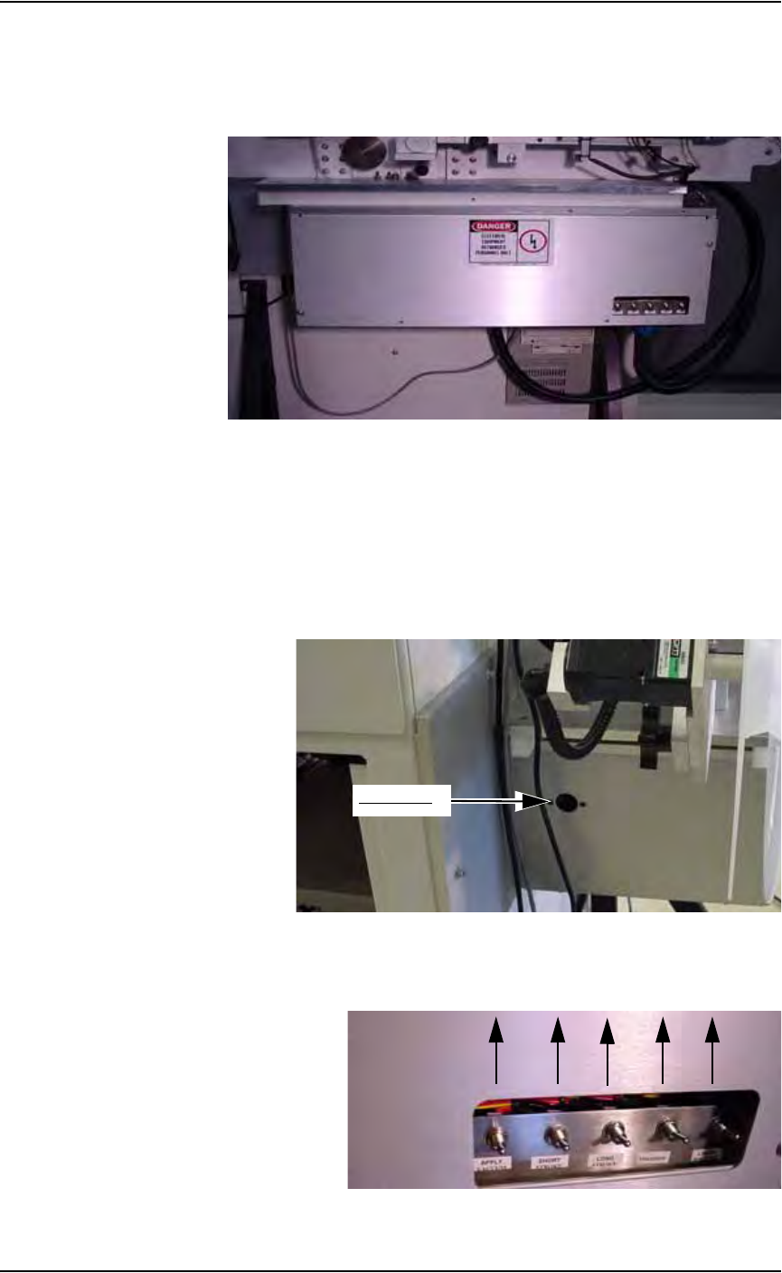
23c) On the PLC controller, press the black reset button located on the left
side of the PLC controller.
Figure 2-37—Reset button
23d) On the front of the controller, toggle UP all switches. This is the “nor-
mal” position. See Figure 2-38.
Figure 2-38—Toggle switches should be in UP (“normal”) position
Reset button

Set Up • (Optional) Setting Up the Label Printing System
2—24 PS288 Owner’s Manual
23e) On the tape output controller, press ESC to enter run mode.
The tape output system is now ready for programmed devices.
24. Replace full take up reel—
When the take up reel is full:
24a) Leave job-specified number of empty pockets on the carrier tape.
24b) Cut the carrier tape.
24c) Roll carrier tape onto take up reel and remove reel.
24d) Install empty take up reel.
24e) Continue job.
(Optional)
Setting Up the
Label Printing
System
The PS288 can be configured with the optional label printing system. To set
up the label printing system, load the media (labels and transfer ribbon) and
install the tamp applicator.
NOTE: For detailed information about the label printing system,
see the Apollo 1 Operator’s Guide and the Apollo 1 Service Man-
ual that came with your label printing system.
If the label printing system is being installed for the first time on your
PS288, the WinAH400.ini file may need to be edited.
1. For first-time installation—
1a) Using Windows Explorer, open C:\AH400_32\WinAH400.ini.with
NOTEPAD editor.
1b) Locate the section
;------- marking system settings -----
1c) Ensure the value for Marking System corresponds to the label printing
system installed on your PS288. For example, if your label printing
system is Apollo, the value should look like this:
;MarkerSystem=M&R
;MarkerSystem=M&R+TAPE
MarkerSystem=BRADY_APOLLO
1d) Save the WinAH400.ini file and exit Windows Explorer.
2. Loading labels and transfer ribbon—
To load labels and transfer ribbon in the label printing system, follow
the loading diagram located on the labeler. See Figure 2-39 for the
location of the loading diagram: