PS288_OwnersMnl_PriorTo2009 - 第67页
Operation • Operat or Functions PS288 Owner’s Manual 3—7 NOTE: Only the Pass Limit information displayed on the Jo b Info tab is editable. T o change the Pa ss Limit , complete S t ep 2 below . 2. Change Pass Limit (opti…
Operation • Operator Functions
3—6 PS288 Owner’s Manual
2. Input 1, 2, 3 and Output 1, 2, 3 media—
Select media for Input 1, 2, 3 and Output 1, 2, 3 with the cycle buttons
to the right of each field. Options vary depending on the selections
made for the main Input and Output media.
3. Reject media—
Select media for Reject 1 and Reject 2. These fields are highlighted in
red.
NOTE: When settings are changed for Input and Output media,
reject media are set to N/A. When Reject Media 1 is changed, Reject
Media 2 is set to N/A. Always set reject media last.
NOTE: Only applicable media are shown depending upon the
mode selected.
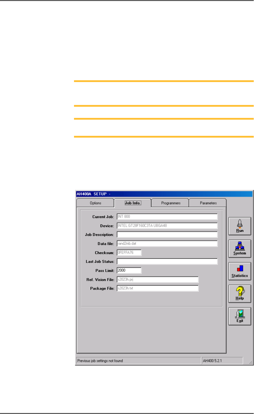
Verify Job Information
1. Select Job Info tab—
1a) On the Setup window, click the Job Info tab.
1b) Verify that all the information displayed matches the information for
this job. See Figure 3-11.
Figure 3-11—Job info
Operation • Operator Functions
PS288 Owner’s Manual 3—7
NOTE: Only the Pass Limit information displayed on the Job Info
tab is editable. To change the Pass Limit, complete Step 2 below.
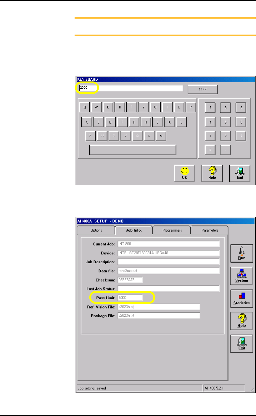
2. Change Pass Limit (optional)—
2a) On the Job Info tab, click on the Pass Limit field. This opens the Key-
board window which displays the current Pass Limit (in this example,
2000).
Figure 3-12—Keyboard window
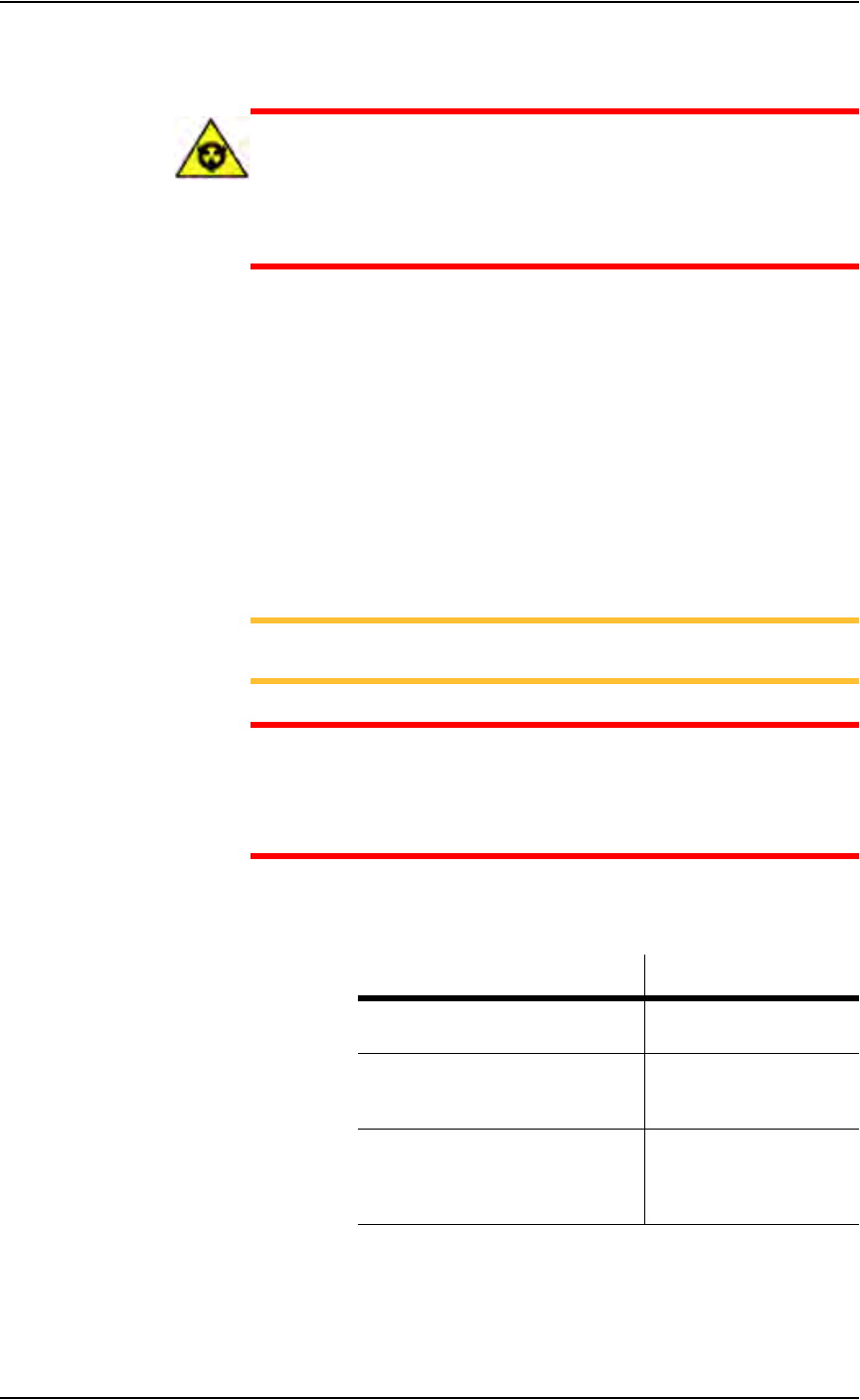
2b) Enter the new Pass Limit value (for example, 5000) and click OK. The
new Pass Limit is then displayed on the Job Info tab. See Figure 3-13.
Figure 3-13—New Pass Limit
Operation • Operator Functions
3—8 PS288 Owner’s Manual
Prepare Input/Output Modules
CAUTION: Devices programmed on the PS288 may be highly sen-
sitive to internal damage from electrostatic discharge (ESD). To
prevent damage from ESD, always wear an antistatic wrist strap.
The wrist strap should be connected to the grounding socket and
should contain a 1M-ohm (minimum value) to 10M-ohm (maximum
value) current limiting resistor.
Regardless of input module used, all devices should be installed
right-side-up (“live bug” orientation), with the device leads pointing toward
the floor so that identifying marks are visible on the top of the device.
The system must be reconfigured if a different device type is programmed or
if the input module (tube, tape, or tray) changes.
When a device is in the pick position waiting for the PNP head, pin 1 on the
device must match the pin 1 orientation predefined in the job. If it does not,
when the PNP head picks the device and rotates it based on the information
in the job, the device might be inserted incorrectly in the socket, possibly
damaging device leads and socket contacts.
NOTE: Ask your system administrator for pin 1 orientation for
trays and tape input as defined by your facility.
CAUTION: Devices and the sockets can be damaged if the devices
at the pick position do not match the pin 1 orientation defined in the
job. Make certain that they are the same. If they are not, do not start
the job until you reinstall the devices in the input module or modify
the job.
If the devices require a different size probe tip, make sure that you install the
appropriate probe tip onto the PNP head as shown below:
Figure 3-14—Selecting probe tip size
For instructions on how to set up the static tray input/output module, see
“Setting Up Static Tray Input/Output” on page 2-5.
If processing this device type: Use this size probe tip:
FBGA
µBGA
Small (2 mm)
300 mil DIP
20 PLCC
32 TSOP
Medium (4 mm)
28 PLCC or greater
40 TSOP or greater
QFP
600 mil DIP
Large (6 mm)