PS288_OwnersMnl_PriorTo2009 - 第69页
Operation • Operat or Functions PS288 Owner’s Manual 3—9 For instructions on how to set up the autom atic tray feeder , see “(Optional) Setting Up the Automatic Tr ay Feeder” on page 2-7. For instructions on how to set u…

Operation • Operator Functions
3—8 PS288 Owner’s Manual
Prepare Input/Output Modules
CAUTION: Devices programmed on the PS288 may be highly sen-
sitive to internal damage from electrostatic discharge (ESD). To
prevent damage from ESD, always wear an antistatic wrist strap.
The wrist strap should be connected to the grounding socket and
should contain a 1M-ohm (minimum value) to 10M-ohm (maximum
value) current limiting resistor.
Regardless of input module used, all devices should be installed
right-side-up (“live bug” orientation), with the device leads pointing toward
the floor so that identifying marks are visible on the top of the device.
The system must be reconfigured if a different device type is programmed or
if the input module (tube, tape, or tray) changes.
When a device is in the pick position waiting for the PNP head, pin 1 on the
device must match the pin 1 orientation predefined in the job. If it does not,
when the PNP head picks the device and rotates it based on the information
in the job, the device might be inserted incorrectly in the socket, possibly
damaging device leads and socket contacts.
NOTE: Ask your system administrator for pin 1 orientation for
trays and tape input as defined by your facility.
CAUTION: Devices and the sockets can be damaged if the devices
at the pick position do not match the pin 1 orientation defined in the
job. Make certain that they are the same. If they are not, do not start
the job until you reinstall the devices in the input module or modify
the job.
If the devices require a different size probe tip, make sure that you install the
appropriate probe tip onto the PNP head as shown below:
Figure 3-14—Selecting probe tip size
For instructions on how to set up the static tray input/output module, see
“Setting Up Static Tray Input/Output” on page 2-5.
If processing this device type: Use this size probe tip:
FBGA
µBGA
Small (2 mm)
300 mil DIP
20 PLCC
32 TSOP
Medium (4 mm)
28 PLCC or greater
40 TSOP or greater
QFP
600 mil DIP
Large (6 mm)
Operation • Operator Functions
PS288 Owner’s Manual 3—9
For instructions on how to set up the automatic tray feeder, see “(Optional)
Setting Up the Automatic Tray Feeder” on page 2-7.
For instructions on how to set up the tube input/output modules, see
“(Optional) Setting Up the Tube Input and Tube Output Modules” on page
2-7.
For detailed instructions on how to set up the tape input and tape output sys-
tems, see “(Optional) Setting Up the Tape Input Feeder” on page 2-10 and
“(Optional) Setting Up the Tape Output System” on page 2-14.
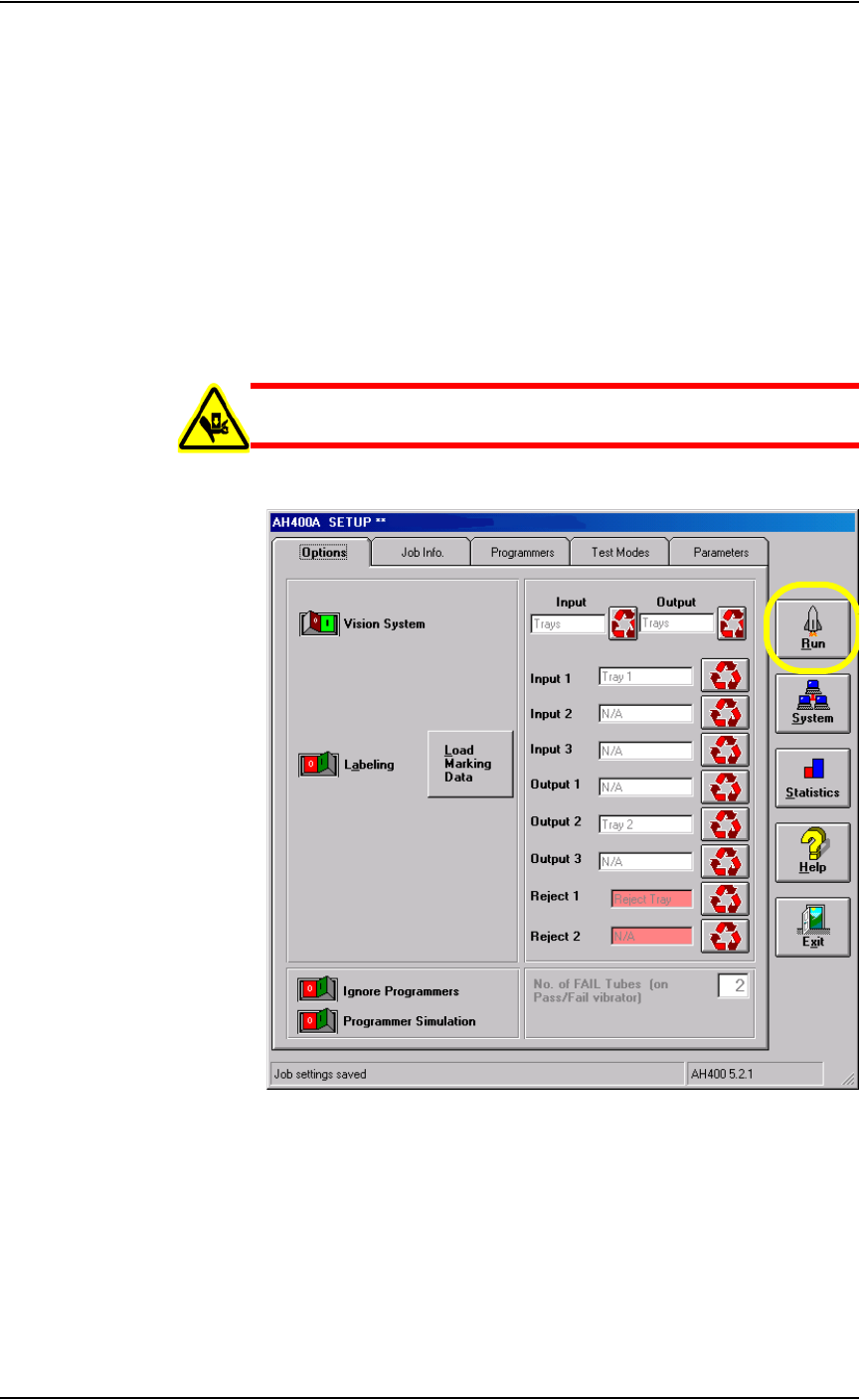
Run a Job
WARNING: Do not continue until making sure that all safety
shields are closed, or personal injury may result.
1. From the Setup window, click Run.
Figure 3-15—Click Run on the Setup window
Operation • Operator Functions
3—10 PS288 Owner’s Manual
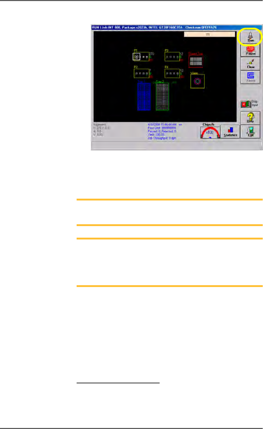
2. On the Run window, click Run.
Figure 3-16— Click Run on the Run window
The PNP head moves to the Park position and then starts the Job. Status
indicators appear inside the programmer outlines, and PNP head loca-
tion is tracked on the Run window.
NOTE: If the input/output media are tubes, you may need to adjust
tube vibration if devices do not move easily. Use the vibration con-
trols on the front of the PS288 to adjust tube vibration.
NOTE: To end a Job after the “pass” media is full, click Stop Input
to the ON position.The Stop Input switch can be selected while a
Job is running. If there are more devices in sockets than empty
spaces in the “pass” media, the system will load an additional tray
or tube before stopping. You can continue a Job stopped in this way
by clicking Run again.
Stop the System
There are three methods for stopping the PS288:
• Emergency Stop and Restart — Stop the movement of the PNP head
in an emergency.
• Pause a Programming Session — Pause a programming session to
perform routine tasks and then resume the programming session.
• End a Job — Complete the current programming cycle, remove
devices from the sockets, and place them into the output media (pass or
reject).
Emergency Stop and Restart
To prevent bodily injury or damage to equipment in an emergency, press
either of the red Emergency Stop (E-Stop) buttons located on the upper