PS288_OwnersMnl_PriorTo2009 - 第81页
Operation • Administrator Functi ons PS288 Owner’s Manual 3—21 • For more information on laser marking, see “(Option al) Create a Laser Marking File ” on page 3-55. • For more information on lab el prin ting, see “(Optio…

Operation • Administrator Functions
3—20 PS288 Owner’s Manual
For more detailed information, see the TF30 Tray Feeder Instruction Manual
that came with your system.
Administrator
Functions
Administrators are responsible for several functions not performed by opera-
tors. In addition to general service and preventive maintenance, administra-
tors would likely perform these functions:
• “Create a Task Using TaskLink” on page 3-20
• “Teach the Reference Vision File” on page 3-21
• “Teach the Package File” on page 3-33
• “Monitor Statistics” on page 3-48
• “Maximize Programming Yields” on page 3-51
• “Monitor Daily Operation Logs” on page 3-53
• “(Optional) Create a Data File from a Master Device” on page 3-54
• “(Optional) Create a Laser Marking File” on page 3-55
• “(Optional) Create a Label Printer File” on page 3-63
Each of these functions will be discussed in this section.
Create a Task Using TaskLink
"Task" is the TaskLink term for a set of instructions to complete a program-
ming Job. Tasks, which are stored in a Task database file (*.TSK), contain all
the information necessary for programming and testing one or more devices
with a particular data pattern. Information contained in a Task includes:
• Device settings - Specific device or a list for operator selection
• Data settings - PC file name
• System settings - Package file name and reference vision file name
• Process settings - Continuity check, electronic ID check, blank check,
erase, verify, program and mark device
NOTE: Once a Task is selected and a Pass Limit is set, the Task is
referred to as a Job to run on PS288.
In addition to containing all device-specific settings, a Task references three
files:
• reference vision file (vision.prj) The reference vision file contains
camera data required to compensate for minor inaccuracies. A refer-
ence vision file template (Vision Template.prj) is included with the
AH500 software. For instructions on how to fill the values for the refer-
ence vision file, see “Teach the Reference Vision File” on page 3-21.
• package file (package.txt) The package file is a text file containing cal-
ibration information that the PNP head uses to properly pick and place
devices. A package file template (PackageTemplate.txt) is included
with the AH500 software. For instructions on how to fill the values for
the package file, see “Teach the Package File” on page 3-33.
• data file (*.hex or *.bin, for example) The data file contains all the
data that will be programmed into the devices.
Options to add, remove, and edit Tasks are found in TaskLink’s Task/Kit
Manager window. Tasks are displayed in the Run Task/Kit window. For
complete instructions on how to create a Task, see TaskLink online Help.

Operation • Administrator Functions
PS288 Owner’s Manual 3—21
• For more information on laser marking, see “(Optional) Create a Laser
Marking File” on page 3-55.
• For more information on label printing, see “(Optional) Create a Label
Printer File” on page 3-63.
Teach the Reference Vision File
The reference vision file contains all the vision system data required by the
PNP head to compensate for minor inaccuracies caused by mechanical varia-
tions in devices, minor errors in the placement of devices on the PNP head,
and other small inaccuracies.
During Task creation, you copied the Vision Template.prj file and renamed it
to the adapter used in the Job. This renamed reference vision file contains the
Vision Template values. Now it is necessary to teach the reference vision file
for the particular device being programmed.
To teach the reference vision file:
1. Prepare the system—
1a) Using TaskLink, load the Job containing the reference vision file you
want to teach.
1b) On the AH500 main window, click Start.
1c) On the Setup window, click System.
NOTE: You may be prompted to enter your Password.
1d) On the System window, click Gantry.
1e) Click the P1 yellow position label representative of Programmer 1. The
gantry will move the PNP head to the location specified.
1f) Adjust the location of the probe tip so that it is centered on the socket.
Use the up/down arrows for Y-axis adjustments and the left/right
arrows for X-axis adjustments. From the inside working outward, the
arrow buttons adjust the position ±0.001, 0.010, and 0.100 inches
respectively.
1g) Click Save.
1h) Click Park to move the PNP head to the Park location.
2. Teach Z drop and Z pick—
2a) Place a device in the socket in Programmer 1.
2b) Click P1 to move the PNP head back to the socket.
NOTE: Adjust the Socket Actuator ribs if required. See Step 4 on
page 3-35.
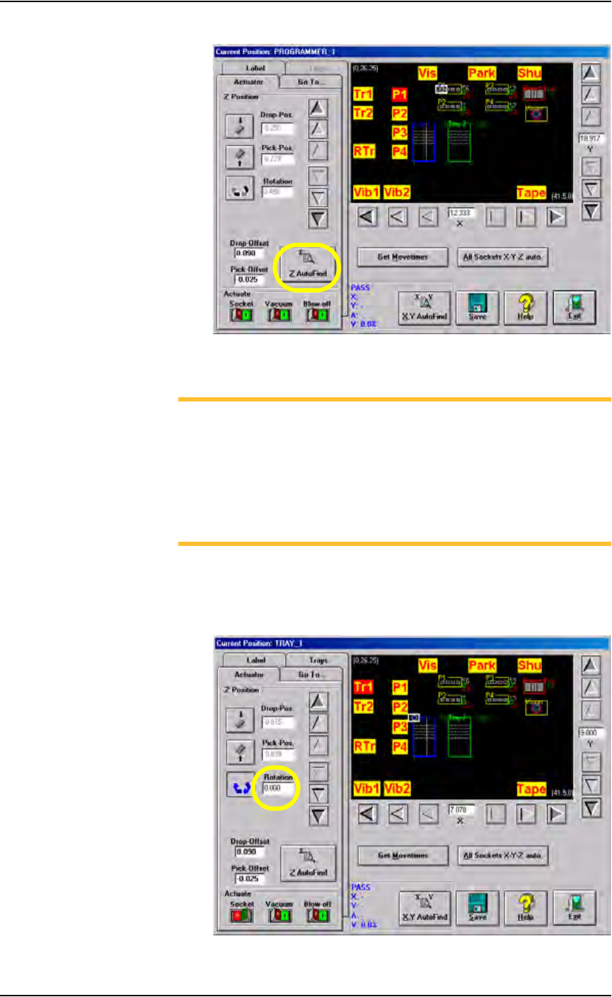
2c) Click Z AutoFind. See Figure 3-26. Ensure that the device is picked
up in the center.
Operation • Administrator Functions
3—22 PS288 Owner’s Manual
Figure 3-26—Click Z AutoFind
3. Set R-axis rotation values
NOTE: When a device is inserted into a socket, pin 1 of the device
must match pin 1 of the socket. For example, if pin 1 of the device
(in the input media) is the upper left corner, and pin 1 of the socket
is the upper left corner, no rotation is required. However, if pin 1 of
the device in the input media is not the same as pin 1 of the socket,
the PNP head must rotate the device. The R-axis value determines
how the PNP head rotates the device as it moves the device from the
input media to the socket or the Vision camera.
3a) Set R-axis of input media to 0.000:
•Click Tr1 to move the PNP head to the Tray 1 location.
• Click the Rotation icon.
• Enter the rotation value 0.000. See Figure 3-27.
Figure 3-27—Rotation set at 0.000 at Tr1