PS288_OwnersMnl_PriorTo2009 - 第91页
Operation • Administrator Functi ons PS288 Owner’s Manual 3—31 10d) Check new Refer ence Position and V erification values. 1 1. Inspect— 11 a ) Cl i c k Inspection on the V i sion System window . Figur e 3-43— Click Ins…
Operation • Administrator Functions
3—30 PS288 Owner’s Manual
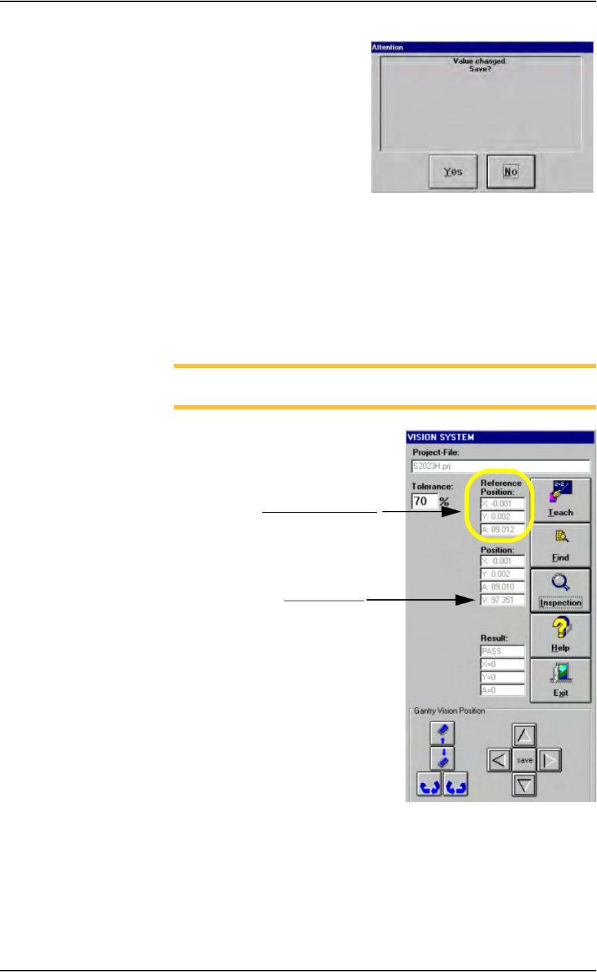
Figure 3-41—Save changed value
9. Check new values—
9a) On the Vision System window, note the new Reference Position val-
ues for X and Y. Values are in inches. Ideally, these values are 0 (zero).
Values of ±0.005 inches are within tolerance. In the example shown
here, X = - 0.001 and Y = 0.002.
9b) Note the Verification value. This value should be greater than 95. In
the example shown here, the value is 97.351.
NOTE: If values are not within tolerance, proceed with Step 10. If
the values are within tolerance, skip forward to Step 11.
Figure 3-42—New values
10. Adjust device image area again (if necessary)—
10a) Adjust the device image area and move it in the X-axis and/or Y-axis
direction as required.
10b) On the Vision System window, click Teach again.
10c) On the Attention message box, click Yes to accept changed values.
Reference Position values
Verification value
Operation • Administrator Functions
PS288 Owner’s Manual 3—31
10d) Check new Reference Position and Verification values.
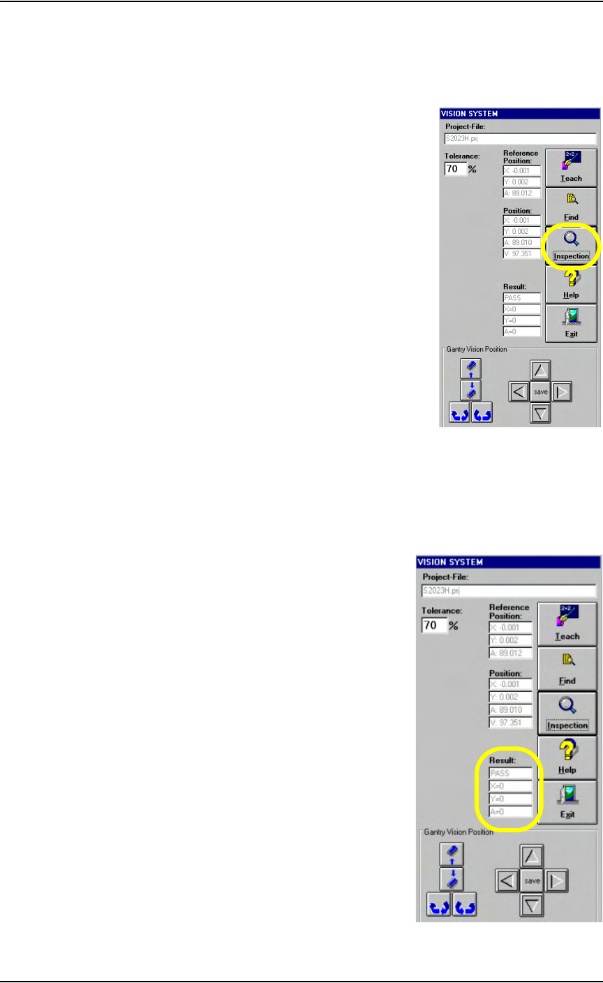
11. Inspect—
11a) Click Inspection on the Vision System window.
Figure 3-43— Click Inspection
11b) Verify that the Result now reads as shown in Figure 3-44.
PASS
X = 0
Y = 0
A = 0
Figure 3-44—Result: PASS
Operation • Administrator Functions
3—32 PS288 Owner’s Manual
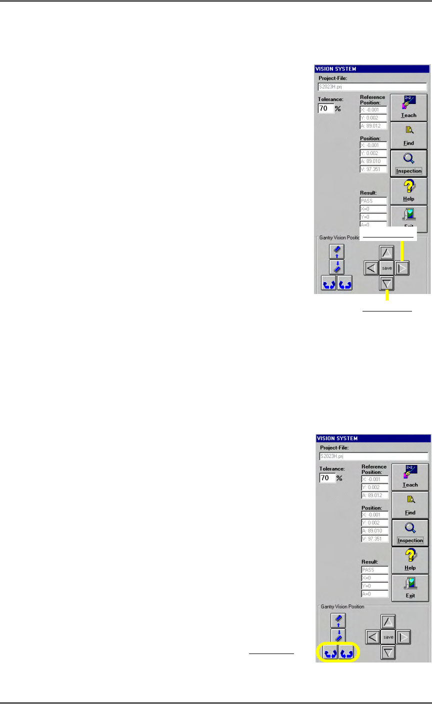
12. Verify reference vision file (optional)—
12a) Move the X-axis and Y-axis two steps (20 mils) by clicking twice on
the forward arrow corresponding to each axis. See Figure 3-45.
Figure 3-45—Forward arrows for X-axis and Y-axis
12b) Click Inspection.
12c) Verify that X = 20, Y = 20 and A = 0.
12d) Move the X-axis and Y-axis two steps back by clicking twice on the
back arrow corresponding to each axis.
12e) Click Inspection.
12f) Verify that X = 0, Y = 0 and A = 0.
12g) Click the Theta rotation button twice. See Figure 3-46.
Figure 3-46—Theta rotation
Forward Y-axis
Forward X-axis
Theta rotation