PS288_OwnersMnl_PriorTo2009 - 第92页
Operation • Administrato r Functions 3—32 PS288 Owner’s Manual 12. V erify reference vision file (optional)— 12a) Move the X-axis and Y -axis two steps (20 mils) by clicking twice on the forward arrow corresponding to ea…
Operation • Administrator Functions
PS288 Owner’s Manual 3—31
10d) Check new Reference Position and Verification values.
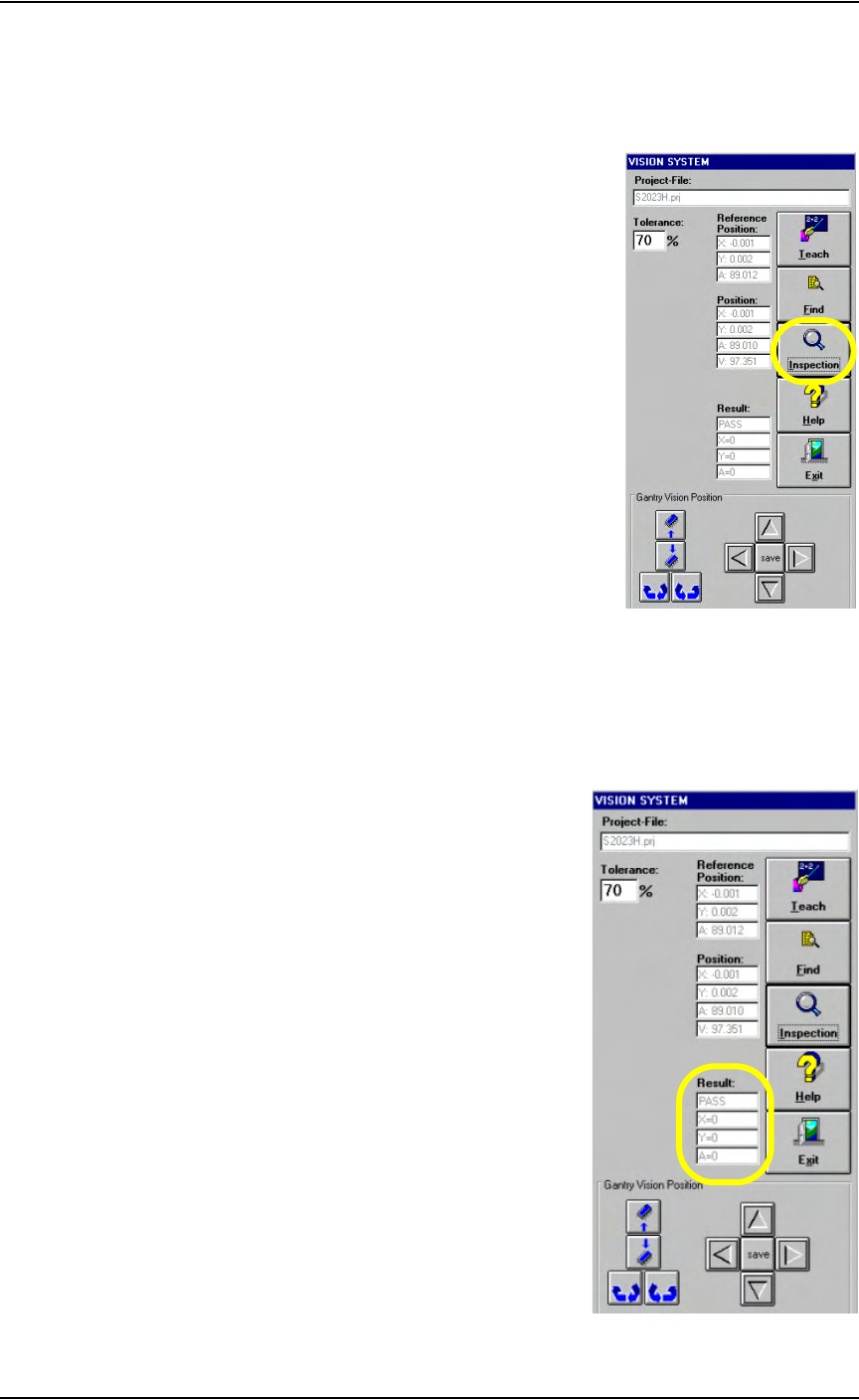
11. Inspect—
11a) Click Inspection on the Vision System window.
Figure 3-43— Click Inspection
11b) Verify that the Result now reads as shown in Figure 3-44.
PASS
X = 0
Y = 0
A = 0
Figure 3-44—Result: PASS
Operation • Administrator Functions
3—32 PS288 Owner’s Manual
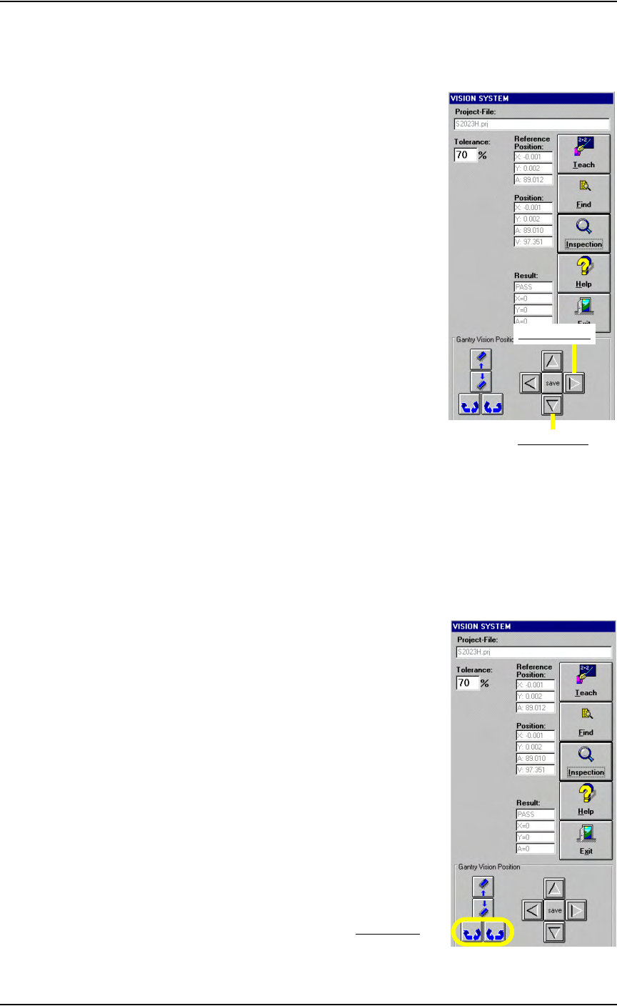
12. Verify reference vision file (optional)—
12a) Move the X-axis and Y-axis two steps (20 mils) by clicking twice on
the forward arrow corresponding to each axis. See Figure 3-45.
Figure 3-45—Forward arrows for X-axis and Y-axis
12b) Click Inspection.
12c) Verify that X = 20, Y = 20 and A = 0.
12d) Move the X-axis and Y-axis two steps back by clicking twice on the
back arrow corresponding to each axis.
12e) Click Inspection.
12f) Verify that X = 0, Y = 0 and A = 0.
12g) Click the Theta rotation button twice. See Figure 3-46.
Figure 3-46—Theta rotation
Forward Y-axis
Forward X-axis
Theta rotation

Operation • Administrator Functions
PS288 Owner’s Manual 3—33
12h) Click Inspection.
12i) Verify that X = 0, Y = 0 and A = 20.
NOTE: If X or Y is more than ±5, then the vacuum cup nozzle is not
correctly positioned. Repeat Step 1 and Step 2 on page 3-21 to
reposition the vacuum cup nozzle.
12j) On the Vision System window, click Exit.
This completes the process of teaching a reference vision file.
Teach the Package File
The package file contains information about the location of all programmers,
all available input media, and the shuttle transfer (if installed). During Task
creation, you copied the PackageTemplate.txt file and renamed it to the
adapter used in the Job (see TaskLink online Help). This renamed package
file contains the Package Template values. Now it is necessary to teach the
package file for the particular device being programmed.
NOTE: If an error button appears on the Gantry window while
teaching the package file, see “Errors” on page 3-45.
To teach the package file:
Teach Programmer Locations
1. Prepare the system—
1a) From TaskLink, select and load the newly created Job.
1b) From the AH500 Setup window, select the Options tab.
1c) For main Input and Output media, select Trays.
1d) For Reject 1, select Reject Tray.
1e) By hand, open the socket on Programmer 1 and insert a device.
NOTE: If Programmer 1 contains more than one socket, insert
devices in the first and last sockets.
1f) On the AH500 Setup window, click System.
1g) On the System window, click Gantry to display a graphic representa-
tion of the work surface, including yellow position labels for all loca-
tions in the work envelope. The Gantry window also includes Y-axis
and X-axis adjustment arrows. See Figure 3-47.