PS288_OwnersMnl_PriorTo2009 - 第94页
Operation • Administrato r Functions 3—34 PS288 Owner’s Manual Figur e 3-47—Graphic r epr esentation of work envelope W ARNING: S tay clear of the ope rating envelope whil e teaching PNP head locations. The PN P head can…

Operation • Administrator Functions
PS288 Owner’s Manual 3—33
12h) Click Inspection.
12i) Verify that X = 0, Y = 0 and A = 20.
NOTE: If X or Y is more than ±5, then the vacuum cup nozzle is not
correctly positioned. Repeat Step 1 and Step 2 on page 3-21 to
reposition the vacuum cup nozzle.
12j) On the Vision System window, click Exit.
This completes the process of teaching a reference vision file.
Teach the Package File
The package file contains information about the location of all programmers,
all available input media, and the shuttle transfer (if installed). During Task
creation, you copied the PackageTemplate.txt file and renamed it to the
adapter used in the Job (see TaskLink online Help). This renamed package
file contains the Package Template values. Now it is necessary to teach the
package file for the particular device being programmed.
NOTE: If an error button appears on the Gantry window while
teaching the package file, see “Errors” on page 3-45.
To teach the package file:
Teach Programmer Locations
1. Prepare the system—
1a) From TaskLink, select and load the newly created Job.
1b) From the AH500 Setup window, select the Options tab.
1c) For main Input and Output media, select Trays.
1d) For Reject 1, select Reject Tray.
1e) By hand, open the socket on Programmer 1 and insert a device.
NOTE: If Programmer 1 contains more than one socket, insert
devices in the first and last sockets.
1f) On the AH500 Setup window, click System.
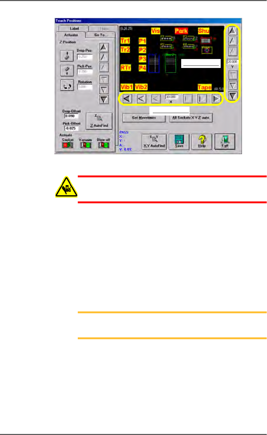
1g) On the System window, click Gantry to display a graphic representa-
tion of the work surface, including yellow position labels for all loca-
tions in the work envelope. The Gantry window also includes Y-axis
and X-axis adjustment arrows. See Figure 3-47.
Operation • Administrator Functions
3—34 PS288 Owner’s Manual
Figure 3-47—Graphic representation of work envelope
WARNING: Stay clear of the operating envelope while teaching
PNP head locations. The PNP head can move without notice
when operating in this mode.
1h) Click P1. The gantry moves the PNP head to the location specified, and
a white box appears on the graphic relative to the PNP head’s physical
location. The position label flashes RED then YELLOW indicating the
position of the PNP head.
2. Adjust location of the probe tip—
2a) Adjust the location of the probe tip so that it is centered on the device.
Use the up/down arrows for Y-axis adjustments and the left/right
arrows for X-axis adjustments. From the inside working outward, the
arrow buttons adjust the position ±0.001, 0.010, and 0.100 inches
respectively. See Figure 3-47.
2b) Click Save.
NOTE: When saved, these settings are kept in the appropriate
package file (.txt) in the directory C:\AH400_32\Package on
the Handler Computer.
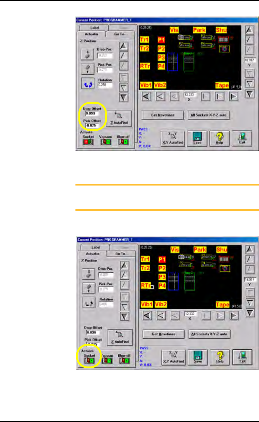
3. Z AutoFind—
3a) Click Z AutoFind. The PNP head lowers and the probe tip touches the
device.
3b) Click Ye s to save the new values.
The Z-axis reference position is now set. From the Z-axis reference, the
drop and pick offsets are added.
For example, if Z-axis reference = -1.000, then:
Zdrop = -0.910 and Zpick = -1.025
See Figure 3-48.
X-axis adjustment
Y-axis adjustment
0.100"
0.010"
0.001"
0.001"
0.010"
0.100"
Operation • Administrator Functions
PS288 Owner’s Manual 3—35
Figure 3-48—Drop and Pick offsets
4. Adjust Socket Actuator (if required)—
NOTE: Adjust the Socket Actuator only if the socket fails to open or
if devices are dropped. It is necessary to adjust the Socket Actuator
only once while teaching a package file.
4a) Click Socket ON. This lowers the Socket Actuator and opens the
socket.
Figure 3-49—Socket ON
4b) On the input panel, push the main air valve down to the OFF position.