PS288_OwnersMnl_PriorTo2009 - 第95页
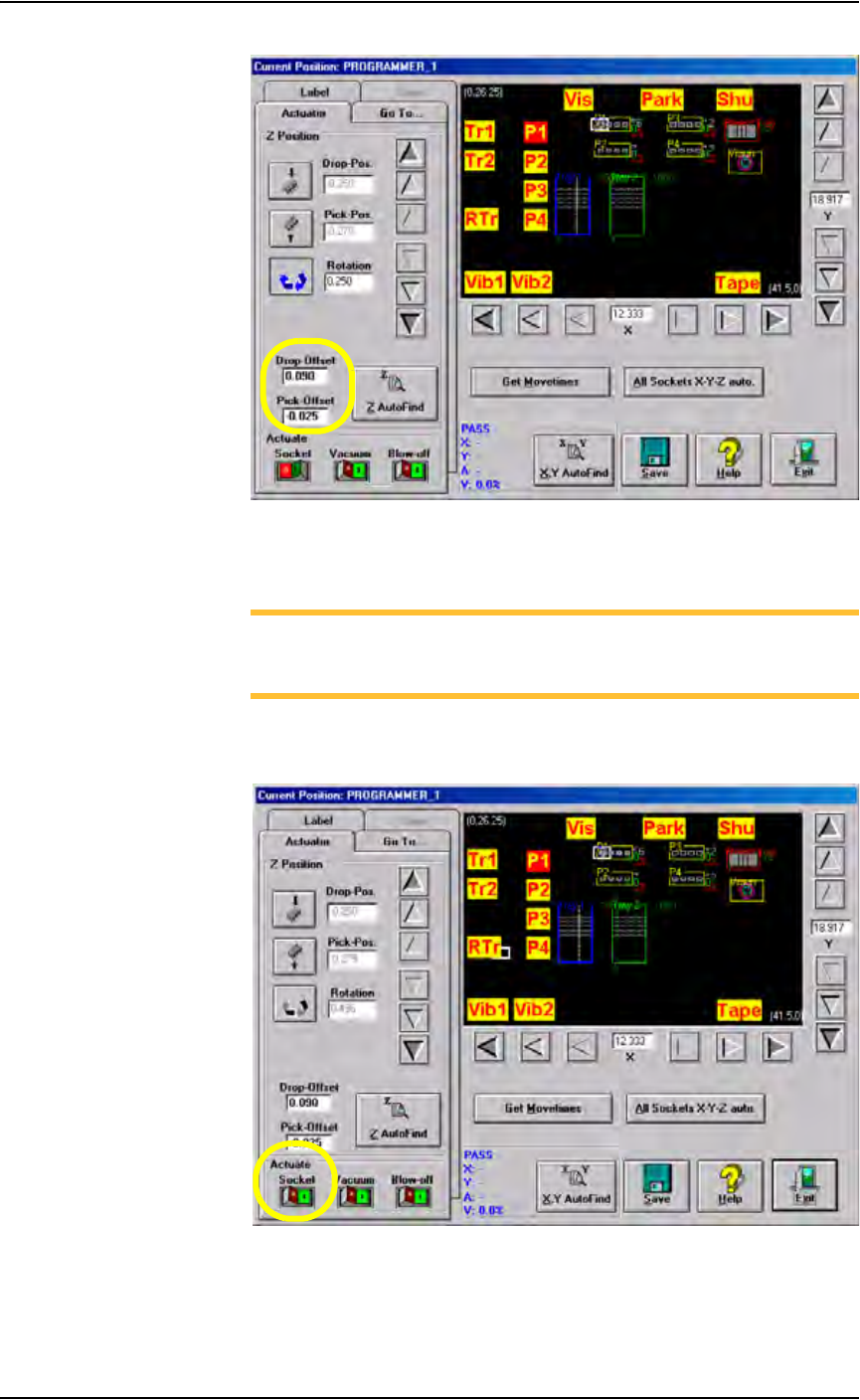
Operation • Administrator Functi ons PS288 Owner’s Manual 3—35 Figur e 3-48— Drop and Pick offsets 4. Adjust Socket Actu ator (if requir ed)— NOTE: Adjust the Socket Actuator only if the socket fails to open or if device…
Operation • Administrator Functions
3—34 PS288 Owner’s Manual
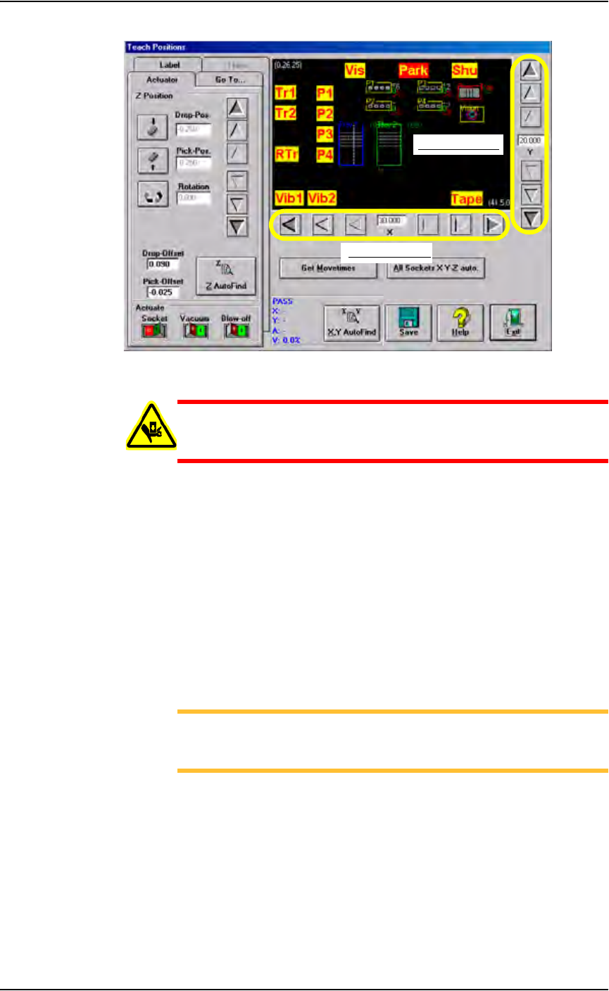
Figure 3-47—Graphic representation of work envelope
WARNING: Stay clear of the operating envelope while teaching
PNP head locations. The PNP head can move without notice
when operating in this mode.
1h) Click P1. The gantry moves the PNP head to the location specified, and
a white box appears on the graphic relative to the PNP head’s physical
location. The position label flashes RED then YELLOW indicating the
position of the PNP head.
2. Adjust location of the probe tip—
2a) Adjust the location of the probe tip so that it is centered on the device.
Use the up/down arrows for Y-axis adjustments and the left/right
arrows for X-axis adjustments. From the inside working outward, the
arrow buttons adjust the position ±0.001, 0.010, and 0.100 inches
respectively. See Figure 3-47.
2b) Click Save.
NOTE: When saved, these settings are kept in the appropriate
package file (.txt) in the directory C:\AH400_32\Package on
the Handler Computer.
3. Z AutoFind—
3a) Click Z AutoFind. The PNP head lowers and the probe tip touches the
device.
3b) Click Ye s to save the new values.
The Z-axis reference position is now set. From the Z-axis reference, the
drop and pick offsets are added.
For example, if Z-axis reference = -1.000, then:
Zdrop = -0.910 and Zpick = -1.025
See Figure 3-48.
X-axis adjustment
Y-axis adjustment
0.100"
0.010"
0.001"
0.001"
0.010"
0.100"
Operation • Administrator Functions
PS288 Owner’s Manual 3—35
Figure 3-48—Drop and Pick offsets
4. Adjust Socket Actuator (if required)—
NOTE: Adjust the Socket Actuator only if the socket fails to open or
if devices are dropped. It is necessary to adjust the Socket Actuator
only once while teaching a package file.
4a) Click Socket ON. This lowers the Socket Actuator and opens the
socket.
Figure 3-49—Socket ON
4b) On the input panel, push the main air valve down to the OFF position.
Operation • Administrator Functions
3—36 PS288 Owner’s Manual
4c) By hand, adjust the Socket Actuator so that the ribs open the socket as
the probe tip descends and so the actuator does not interfere with the
device as it is picked up by the probe tip.
4d) On the input panel, push the main air valve up to the ON position.
4e) Click Socket OFF to raise the Socket Actuator.
5. Set R-axis value—
Follow the instructions in “Set R-axis rotation values” on page 3-22.
6. Pick the device—
6a) Click P1 to return the PNP head to Programmer 1.
6b) Press X,Y AutoFind. The PNP head picks the device, takes it to the
vision location and compares the orientation of the device to the orien-
tation in the reference vision file.
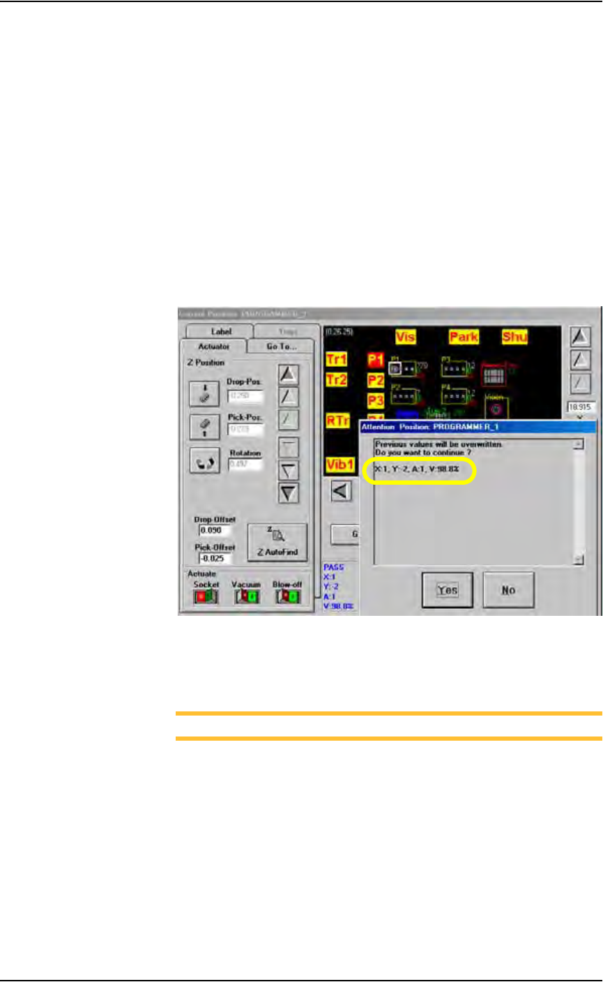
6c) When the Attention message box pops up, check the Results informa-
tion.
Figure 3-50—Results information
6d) If the new values for X and Y are >±5, press Ye s and repeat Step 6b.
If the new values for X and Y are <±5, press No.
NOTE: If the programmer has multiple sockets, complete Step 7.
7. Multiple socket programmers—
7a) On the Go To tab, click last Socket. See Figure 3-51.