Apollo1_Operators_Manuel.pdf - 第22页
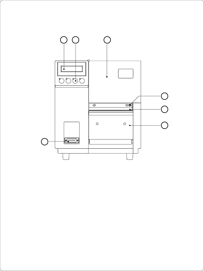
22 cab - Produkttechnik GmbH / Tharo Systems, Inc. 1 - Display 2 - Function keys with indicator LEDs 3 - Cover 4 - Ribbon shield screw 5 - Ribbon shield 6 - Dispense/ T ear-of f plate 7 - Peripheral port Fig. 4 a Front v…

21cab - Produkttechnik GmbH / Tharo Systems, Inc.
2 General Safety Instructions
- The printers of the Apollo series are built exclusively to print labels and
tags, continuous paper, etc. Do not use other materials than listed in
Chapter 1.
- Connect the printer only to an outlet with the correct voltage !
The printer is configured for either 230V or 115V power supply, which can
be switched using the input voltage selector at the back of the printer.
Connect only to a power outlet with a grounded contact.
- The printer must only be connected to devices which have extra low
voltage.
- Power must be OFF before plugging in any accessory or connecting the
printer to a computer, etc. Also switch power off on all appliances before
disconnecting.
- Do not expose the printer to any moisture, or use in damp or wet areas.
- The printer will operate with the cover open if necessary. This is not
recommended, as moving or rotating parts become accessible. Keep long
hair, jewelry, loose clothes away from the moving parts.
- During the print process the printhead will become hot. Use extra caution
when touching the printhead.
3 Unpacking and Delivery Contents
Inspect the Apollo's packaging and contents immediately after receipt for possible
damage caused by shipping.
The supplied equipment of the Apollo depends on the requested options.
Compare the delivered accessories with your order.
Please keep the original packaging in case the printer must be returned.
F
22 cab - Produkttechnik GmbH / Tharo Systems, Inc.
1 - Display
2 - Function keys with indicator LEDs
3 - Cover
4 - Ribbon shield screw
5 - Ribbon shield
6 - Dispense/ Tear-off plate
7 - Peripheral port
Fig. 4 a Front view
4 Printer Component Location
1 2 3
4
5
6
7
23cab - Produkttechnik GmbH / Tharo Systems, Inc.
54321
6 7 8
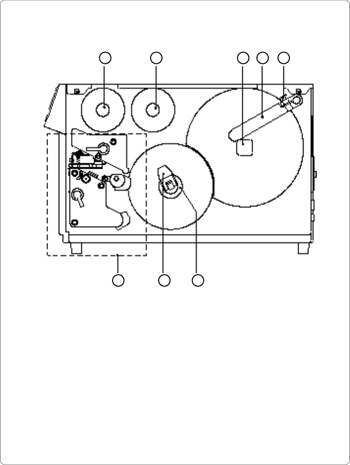
Fig. 4 b Side view Apollo 1 (with cover open)
1 - Ribbon take up hub
2 - Ribbon supply hub
3 - Media hub
4 - Media retainer
5 - Media retainer knurled head screw
6 - Print mechanism (for details see Figure 4 c)
7 - Media rewind locking lever
8 - Media rewind hub