Apollo1_Operators_Manuel.pdf - 第30页
30 cab - Produkttechnik GmbH / Tharo Systems, Inc. Fig. 5 b Interface ports (detailed view/ rear of the printer) Apollo 1/2 Apollo 3 1 2 1 2 1 - Parallel interface port 2 - Serial interface port Connection to a Computer …
29cab - Produkttechnik GmbH / Tharo Systems, Inc.
5 Connecting the Printer
Connection to Power Supply
1
2
4
3
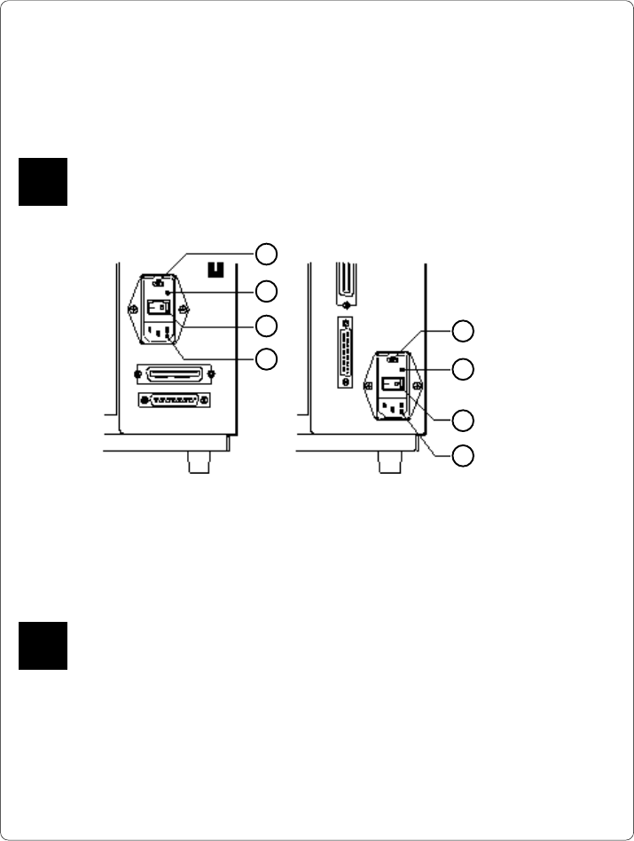
Fig. 5 a Power supply module (detailed view/ rear of the printer)
To change the voltage setting, open the cover (2) and remove the voltage
selector from the power unit.
If you have changed the operating voltage of your printer the fuses need
replacing as stated below !
Apollo 1/2 : 230V - 2 x T 3.15A 115V - 2 x T 6.3A
Apollo 3 : 230V - 2 x T 1.6A 115V - 2 x T 3.15A
When delivered, the correct fuses for the pre-selected operative voltage are
installed. You will find the necessary fuses for the other voltage in the
accessories package.
Slide the voltage selector back into the power supply module so that the
correct voltage is visible in the lid window (2).
Connect the printer to a grounded outlet using the power cable supplied in the
accessories package.
F
1
2
3
4
1 - Voltage selector
2 - Voltage selector
cover
3 - Power switch
4 - Power supply
connector
Apollo 1/2 Apollo 3
The Apollo is designed for use with 230V A.C/ 50Hz (standard) or 115V A.C/
60Hz.
Before connecting the printer to the power supply, make sure that the
voltage selected on the power supply module of the printer is the same as
your main power supply !
F
30 cab - Produkttechnik GmbH / Tharo Systems, Inc.
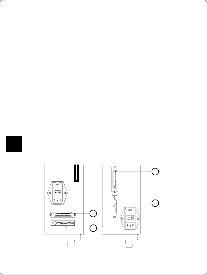
Fig. 5 b Interface ports (detailed view/ rear of the printer)
Apollo 1/2 Apollo 3
1
2
1
2
1 - Parallel interface port
2 - Serial interface port
Connection to a Computer
The Apollo is equipped with three serial interfaces, these are RS-232, RS-422,
and RS-485, all of them using the 25 pin interface connector (2) at the back.
In most cases, you can use the RS-232 interface for the connection to the
computer. If your computer is located more than 50 ft (15m) away from the
printer you should use the RS-422 interface.
The RS-485 interface is provided for using the Apollo as part of a networked
system.
In addition to the serial port, the Apollo also provides a parallel (Centronics)
interface which offers a faster transfer of data than the serial interfaces.
Therefore, we recommend you use the parallel interface for those applications
where a large number of loadable fonts or complex graphics have to be printed.
For the Centronics interface use the 36 pin interface connector (1).
Select the required interface settings using the Setup procedure (
see Chapter 9
)
and connect the printer to the computer by a suitable interface cable. You will find
a list of typical cables as well as a description of the pin assignment of the interface
connectors in Appendix B.
Make sure that all connected computers and their connecting cables are
correctly grounded.
F
31cab - Produkttechnik GmbH / Tharo Systems, Inc.
6 Media Loading
Loading Labels
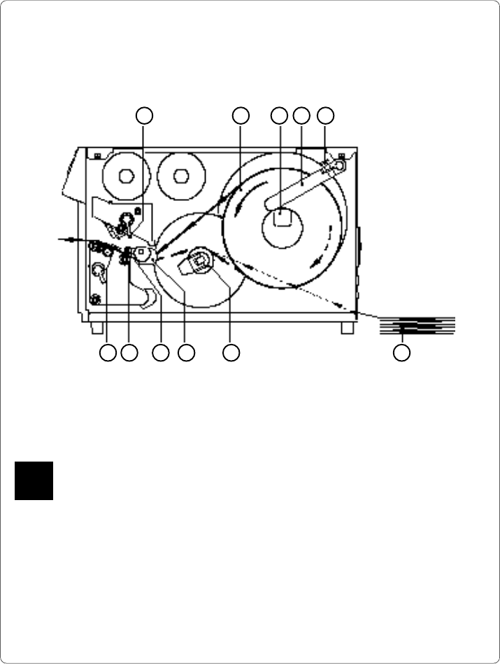
1 2 3 4 5
6789 1011
Fig. 6 a Media Loading Apollo 1
1. Lift the printhead by rotating the lever (1) clockwise until it stops.
With Apollo 1, the printhead lever (1) has to be rotated by approximately 260°.
Only if the swing movement has been completed will the upper pinch roller (10)
be removed from the lower pinch roller (11), and the entire area is opened for
loading the media.
2. Loosen the media retainer knurled screw (5) and swing the media retainer
(4) upwards.
3. Place the label roll (2) onto the media hub (3).
The solid line represents the feed path of outside-rolled labels, the broken line
of inside-rolled labels. The broken-dotted line shows the media path of fanfold
paper (6). For printers with internal rewinder, pay special attention that the
media is properly fed above the internal rewind hub (7) when loading.
F