Apollo1_Operators_Manuel.pdf - 第36页
36 cab - Produkttechnik GmbH / Tharo Systems, Inc. Adjustment of the T ransfer Ribbon Fig. 7 c Adjustment of the transfer ribbon If creases, lines or black patches appear in the print image resulting in a poor print qual…
35cab - Produkttechnik GmbH / Tharo Systems, Inc.
Adjustment of the Printhead Support
4
2
4
1 1
Apollo 1 Apollo 2/3
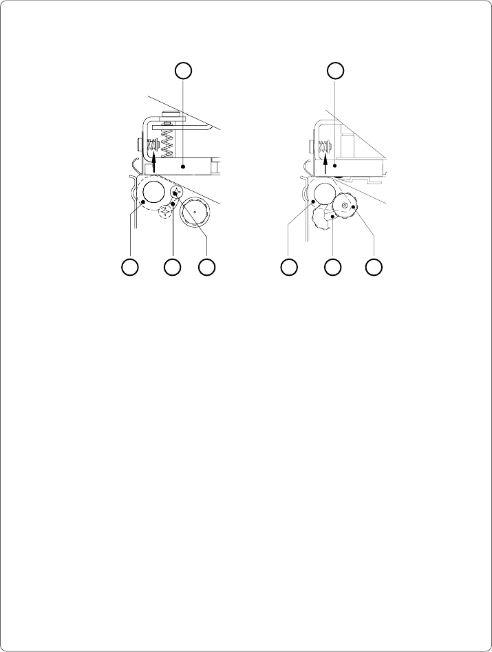
Fig. 7 b Adjustment of the printhead support
When printing narrow labels (width less than 2.5 in or 60 mm), it is possible that
the printhead will come into direct contact with the drive roller. This will lead to
premature wear on the printhead. In addition, the printhead will be at a slight
angle to the label, thus, the uneven pressure may result in an inconsistent
image density from one edge of the label to the other.
To correct this problem, the printhead support (2) may be adjusted.
Adjust printhead support as follows :
1. Loosen the locking screw (2). For Apollo 1, this screw is an oval-headed
screw, whereas for Apollo 2/3 it is a knurled screw.
2. Move the locking screw (2) as required within the adjustment slot (3). This
will cause the cam shaped printhead support (4) to rotate, in effect,
providing a higher or lower base on which the printhead mounting (1) rests.
As the adjustment criterion, check the quality of the print image.
3. Tighten the locking screw (2).
3 3
2
36 cab - Produkttechnik GmbH / Tharo Systems, Inc.
Adjustment of the Transfer Ribbon
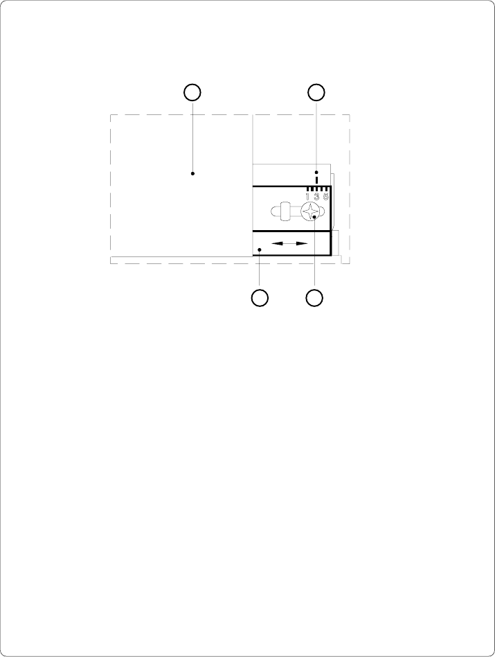
Fig. 7 c Adjustment of the transfer ribbon
If creases, lines or black patches appear in the print image resulting in a poor
print quality, this may be caused by wrinkles in the transfer ribbon (1). To
remove the wrinkles, the tension of the ribbon should be made even from the
left to the right by moving the ribbon shield (4) up or down.
1. Loosen the adjustment screw (3).
2. Shift the transfer ribbon shield (4) sideways into the direction of the wrinkle.
Moving it to the left will increase the tension on the left.
Use the scale (2) provided to monitor the adjustments made. If the screw
is in position "1", the tension is highest on the outside, and if it is in position
"5", the tension is highest on the inside.
3. After completing the adjustment, tighten the securing screw (3).
1 2
34
37cab - Produkttechnik GmbH / Tharo Systems, Inc.
8 Control Panel
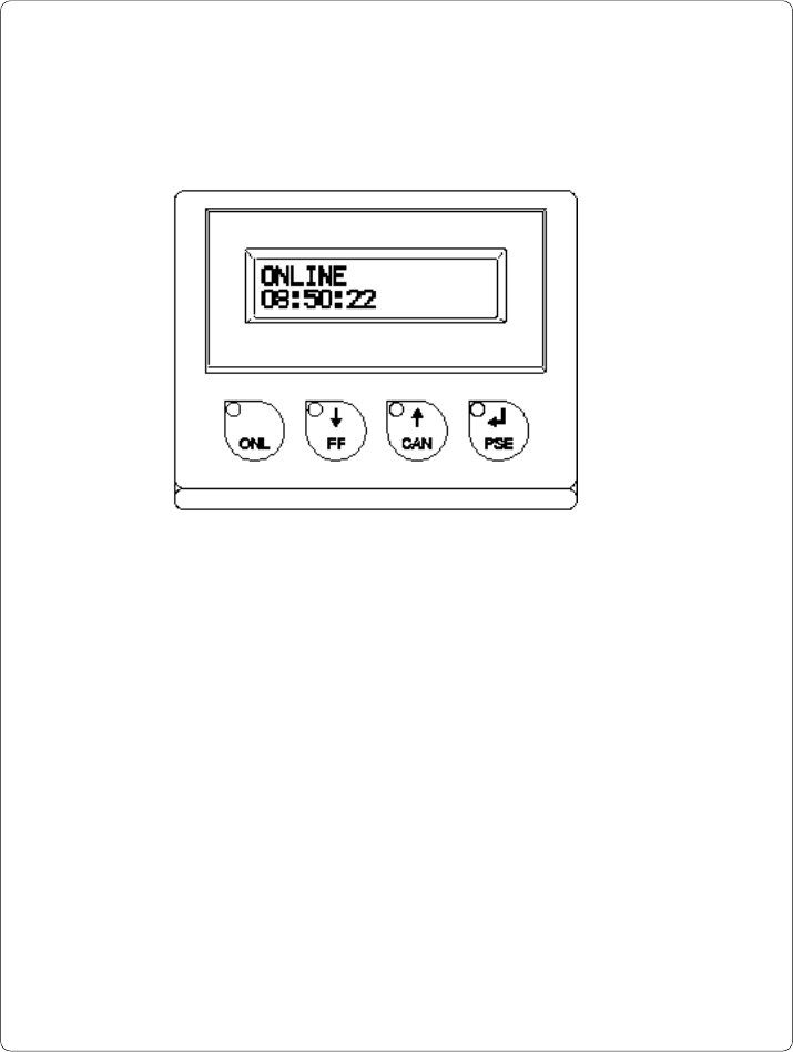
Fig. 8 Front control panel
The front control panel of the Apollo is fitted with 4 function keys with indicator
LEDs, and a 2x16 character digital LCD display.
The control panel display constantly provides the operator with the actual
information concerning the current printer mode and label processing. The
indicator LEDs support the information shown in the display by indicating which
keys have to be pressed. (e.g. in the event of a fault)
On the following pages, you will find descriptions of the system modes of the
Apollo, the related indications by the LCD display and the LEDs as well as a
description of the function keys under differing conditions.