Apollo1_Operators_Manuel.pdf - 第77页
77 cab - Produkttechnik GmbH / Tharo Systems, Inc. Code Druck Code Druck Code Druck Code Druck DEC HEX DEC HEX DEC HEX DEC HEX 00 00 08 08 16 10 24 18 01 01 09 09 17 1 1 25 19 02 02 10 0A 18 12 26 1A 03 03 1 1 0 B 19 13 …
76 cab - Produkttechnik GmbH / Tharo Systems, Inc.
Printer info
4: 0000 / 3 / 5 / C
Fig. 11 d Printer info display 4
The fourth page of the info display contains coded information on the configuration of
the printer and the internal test results in the format "xxxx / y / z / C".
xxxx Result of the system test
The four-digit hexadecimal number contains (coded) hardware faults.
The figure is the same as in the printout of the self test.
For fault encoding see code Table 10 in chapter 10 "Self Test".
The example, as shown in Figure 11d, displays "0000" indicating that
there have been no hardware faults.
y Type of peripheral device
0 : Cutter
2 : Applicator
3 : None fitted
4 : External print start
For example, Figure 11 d : "3" - No peripheral device connected.
z Configuration setting Transfer print/ Label sensor
The value of z results from adding the code numbers for selected settings.
Transfer print : 1 = ON
0 = OFF
Label sensor : 8 = Bottom-Reflect
4 = Gap sensor
0 = Top-Reflect
For example, Figure 11d : "5" - Transfer print ON (1) + Gap sensor (4).
C Indicates that the setup configuration has been altered from the defaults, for
Apollo 1 and Apollo 2 only. (no other messages)
For Apollo 3, the letter behind the "/" sign represents the state of modification
of the hardware. (board)
Printer info
5: ISO 8859-1
Fig. 11 e Printer info display 5
The last of the info pages shows the name of the character set as selected in setup.
77cab - Produkttechnik GmbH / Tharo Systems, Inc.
Code Druck Code Druck Code Druck Code Druck
DEC HEX DEC HEX DEC HEX DEC HEX
00 00 08 08 16 10 24 18
01 01 09 09 17 11 25 19
02 02 10 0A 18 12 26 1A
03 03 11 0B 19 13 27 1B
04 04 12 0C 20 14 28 1C
05 05 13 0D 21 15 29 1D
06 06 14 0E 22 16 30 1E
07 07 15 0F 23 17 31 1F
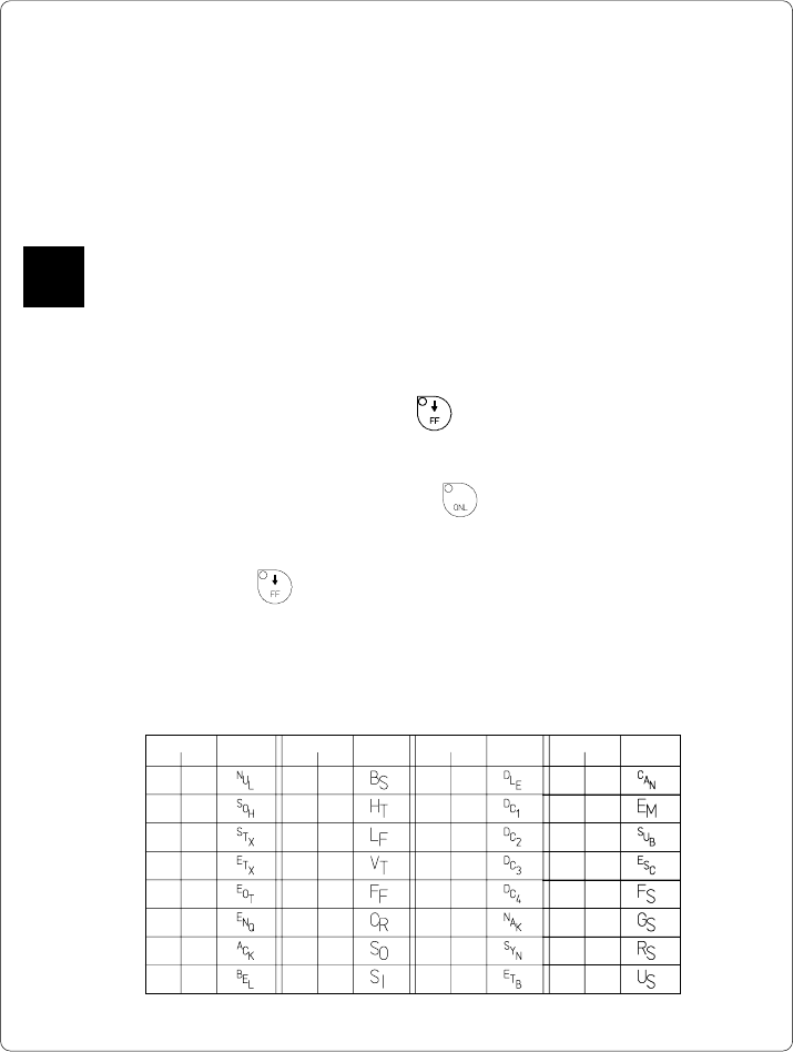
Table 12 Representation of the control characters in monitor mode
12 Monitor Mode/ ASCII Dump Mode
If programming directly, the monitor mode provides a method to print control
sequences which were received at the interface. The commands will be printed in
text format depending on the selected character set. Error messages will be
printed directly behind the fault, e.g. for unknown commands.
In monitor mode, the Apollo will not recognize gaps between labels nor control the
ribbon feed.
The font used for printouts in monitor mode is suitable to send by facsimile.
For questions or future reference, print and retain one copy of the label format for
each label printed.
Start of Monitor Mode/ ASCII Dump Mode
To start the monitor mode, press the key while switching on the printer, and
keep it pressed down until the system test is completed. The display shows
"ASCII Dump Mode".
To cancel ASCII Dump mode, press the key.
In monitor mode, the print of data will be started after every four lines of data
received. Therefore, in some cases, the last lines of the label have to be retrieved
by pressing the key.
Representation of the Control Characters
The control characters (ASCII Code 00 ... 31) as shown in monitor mode
printouts are as follows.
F
78 cab - Produkttechnik GmbH / Tharo Systems, Inc.
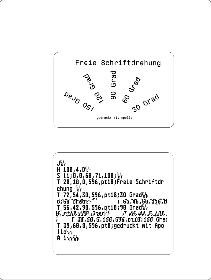
Example of ASCII Dump Mode
The following figures show the "normal" appearance of a printed label, and the
appearance of the same label when its commands are printed in ASCII Dump
mode.
Fig. 12 a "Normal" label
Fig. 12 b The same label as above printed in ASCII Dump mode