Apollo1_Operators_Manuel.pdf - 第80页
80 cab - Produkttechnik GmbH / Tharo Systems, Inc. Safety Instructions The printer must be powered OFF before mounting the rewinder . During operation, the rotating axle is openly accessible ! Therefore, keep long hair ,…
79
cab - Produkttechnik GmbH / Tharo Systems, Inc.
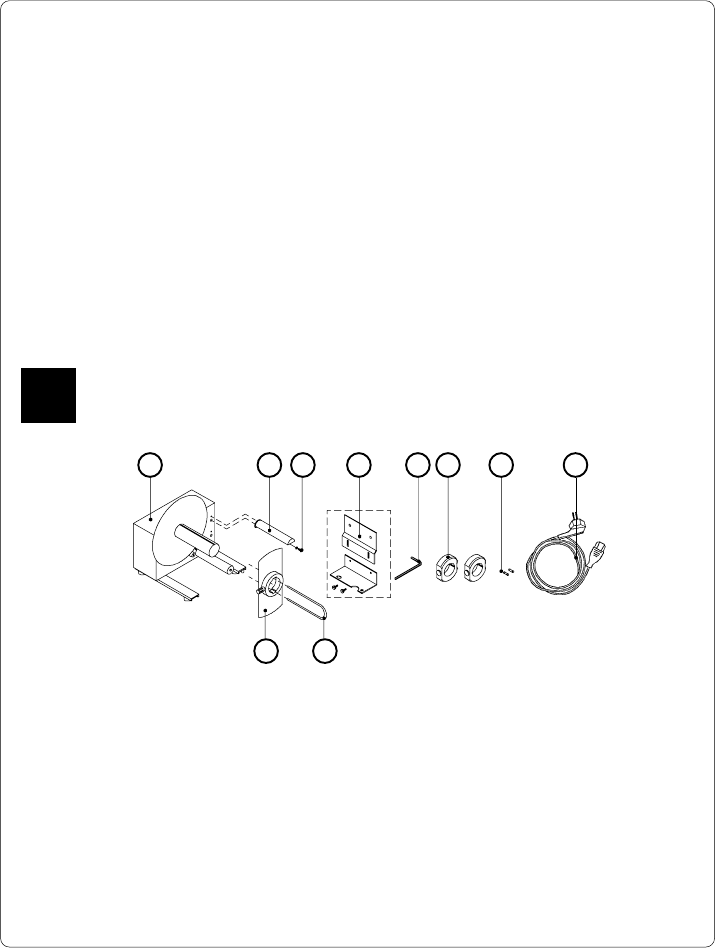
Fig. 13 a Package contents of the external rewinder
85 6 7
13 Options
External Rewinder
To handle large print jobs, an external rewinder is available which allows you to
rewind complete rolls of label material. The maximum size of the media supply roll
is 8 in (200 mm) with a core diameter of 3 in (75 mm), or a roll of 7.5 in (190 mm)
with a core of 1.5 in (40 mm).
The external rewinder is mechanically connectable to the Apollo by an adapter
plate. The rewinder requires a separate power outlet for its operation.
Delivery Contents
The rewinder is packed separately from the printer.
Please keep the original packaging in case the rewinder must be returned !
The following components are included in the package :
1 2 3 4
10 9
1 - Rewinder
2 - Guide bar
3 - Cylinder screw M5x10 incl. washer A5.3
4 - Printer adapter
(upper adapter plate, lower adapter plate, 2 knurled screws M4x6)
5 - Hexagonal wrench (.16 in or 4 mm)
6 - 2 Rewind axle adapters, with a diameter of 3 in or 75 mm
7 - 2 x 1A Fuses (for use at 115V)
8 - Power cable
9 - Clamp
10 - Flange
F
80 cab - Produkttechnik GmbH / Tharo Systems, Inc.
Safety Instructions
The printer must be powered OFF before mounting the rewinder.
During operation, the rotating axle is openly accessible !
Therefore, keep long hair, loose clothes, and jewelry away from the moving parts !
Before connecting the rewinder to the power supply, make sure the voltage
selected on the power module corresponds with the supply voltage !
F
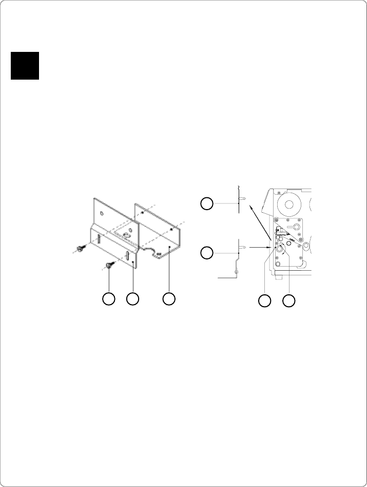
Mounting the Printer Adapter
In order to operate the external rewinder, an adapter unit has to be mounted on to
the Apollo.
Fig. 13 b Mounting the printer adapter
1. Attach upper adapter plate (2) to the lower adapter plate (3) using the
knurled screws (1). Put the screws through the circular holes in the upper
adapter plate.
2. Rotate the accessory lock/release lever (7) counter-clockwise until it stops.
3. Remove the tear-off plate (4) from its mountings (6).
4. Insert the printer adapter plate (5) into the mountings (6).
5. Turn the lock/release lever (7) clockwise until it stops.
6. Adjust the lower adapter plate (3) vertically until only a space of about .08
in or 2 mm is left between the adapter plate and the standing area.
7. Tighten the screws (1).
4
5
6 7
1 32
81
cab - Produkttechnik GmbH / Tharo Systems, Inc.
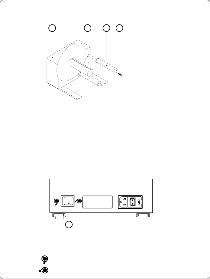
Set the switch (5) to the required method of rewinding :
- Rewind with labels on the outer side of the silicon liner
- Rewind with labels on the inner side of the silicon liner
Mounting the Guide Bar
1 2 3 4
1 - Rewinder
2 - Upper threaded hole
3 - Guide bar
4 - Screw (incl. washer)
Fig. 13 c Mounting the guide bar
Using the hex screw (4) and washer provided, secure the guide bar (3) into the
upper one of the two threaded holes (2) located on the inside of the rewinder's side
cover. A hexagonal wrench is provided.
Selecting the Method of Rewinding
The external rewinder allows rewinding of labels in both ways, inside and
outside winding.
5
Fig. 13 d Selecting the method of rewinding