Apollo1_Operators_Manuel.pdf - 第90页
90 cab - Produkttechnik GmbH / Tharo Systems, Inc. 1. Lift the printhead by turning the lever ( 7 ) clockwise until it stops. 2. Loosen the knurled screw ( 11 ) and swing media retainer ( 10 ) upwards. 3. Place the media…
89
cab - Produkttechnik GmbH / Tharo Systems, Inc.
Present Sensor
The optional present sensor in connection with printers with internal rewinder
allows for on-demand label dispensing. That means, the labels are removed
from the silicon liner immediately after printing, and then available in a dis-pense
position ready for further processing.
The present sensor (2) consists of two components, the dispense edge (18)
and the present sensor photocell (6). The presence of a label (19) in dispense
position is observed by the photocell. Through its connection to the peripheral
port of the Apollo, the signal pauses the print of the next label until the label in
the dispense position is removed.
Note : When editing or creating labels in demand mode, make sure that the
part of the label which lies directly underneath the photocell is only colored (black)
to a maximum of 50%. Higher blackening/ density print may cause malfunctions of
the sensor.
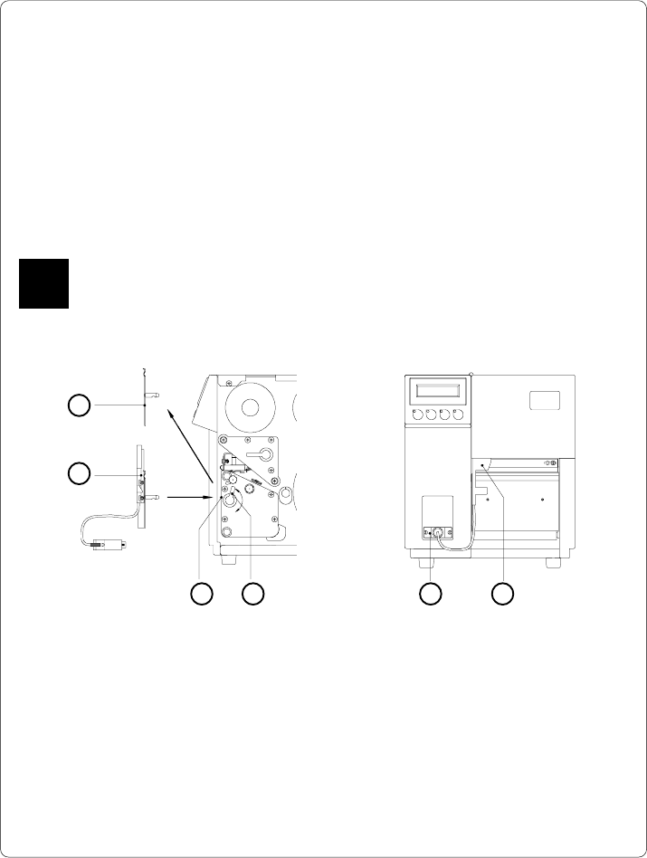
Mounting of the Present Sensor
43 5 6
Fig. 13 m Mounting of the present sensor
The Apollo is generally shipped with the tear-off plate (1) mounted. When
operating in dispense mode, the tear-off plate has to be replaced with the
present sensor (2) :
1. Turn lever (4) counter-clockwise until it stops.
2. Remove the tear-off plate (1) from the mounting holes (3).
3. Slide the present sensor (2) into the mounting holes (3).
4. Turn lever (4) clockwise until it stops.
5. Connect the cable (5) of the present sensor (6) to the 15 pin peripheral port of
the Apollo.
2
1
F
90 cab - Produkttechnik GmbH / Tharo Systems, Inc.
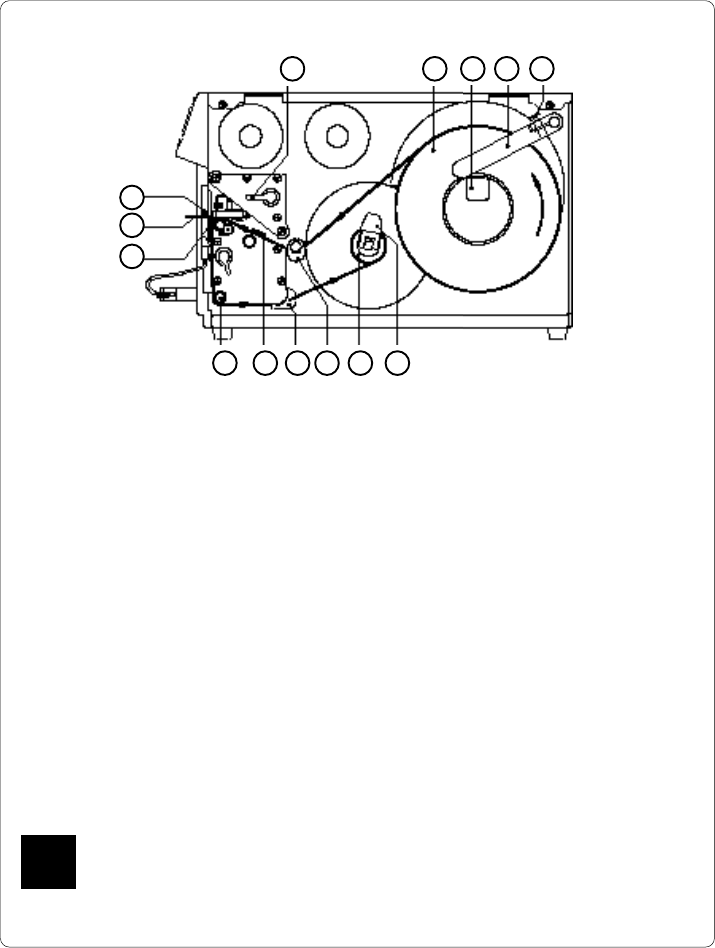
1. Lift the printhead by turning the lever (7) clockwise until it stops.
2. Loosen the knurled screw (11) and swing media retainer (10) upwards.
3. Place the media roll (8) onto the media hub (9). Swing the media retainer
(10) downwards and inwards until it rests against the side of the roll.
Tighten the knurled screw (11).
4. Slide the two media guides (14/15) to their outermost position.
5. Unroll a length of media stock and feed it through the Apollo as shown in
Figure 13 n. It is particularly important to ensure that the media strip slides
properly between the adjustable fittings of the photocell assembly (16).
6. Feed the media strip between the print roller and the thermal printhead,
and then over the dispense edge (18) up to the internal rewinder (13).
7. Turn the locking lever (12) of the internal rewinder towards the axle to
release the expanding axle. Slide the media strip underneath the rewinder
clamps up to the rewinder plate. Expand the axle by turning the lever (12)
back to its original position. Rotate the rewinder counter-clockwise to tighten
the media strip.
8. Slide the two media guides (14/15) against the edge of the media strip.
9. Lock the printhead by turning the lever (7) counter-clockwise until it stops.
If you do not use the printer for an extended period of time, lift the printhead to
avoid possible flattening of the print roller.
Fig. 13 n Inserting the labels for peel-off
F
121314151617
Inserting the Labels for Peel-off
7 8 9 10 11
18
19
6
91
cab - Produkttechnik GmbH / Tharo Systems, Inc.
Memory Cards
The printers of the Apollo series provide an option for using memory cards to
permanently save graphics, fonts, complete label formats, or database
information. Data transfer may be performed via interface. Alternatively, the
printer is able to read from cards which has been written on in PC card drives
of lap-tops or other computers, etc.
The Apollo is able to read from PCMCIA version 2.1 compatible sRAM cards
or Flash-EPROM cards. The maximum memory capacity for Apollo 1/2 is 4
MegaByte, and for Apollo 3 16 MegaByte.
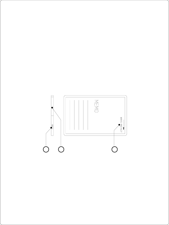
Preparing the Memory Card
1 2 3
Fig. 13 o Write protection/ Inserting the battery
The write protection of the card may be activated or deactivated by shifting the
switch (1) located at the front side of the card. The interpretation of the setting
may be read from an imprint (3) on the back of the card.
If you want to format the card or write on it, switch off the write protection.
In case the battery has to be replaced, it is usually found in a slot (2) above the
switch (1).
For replacing or inserting the battery in sRAM cards refer to the instructions of
the manufacturer.