YG200_200L_E.pdf - 第35页
1-7 1 Part names and functions 2 . 2 O p e r a t i o n p a n e l b u t t o n s T h e o p e r a t i o n p a n e l b u t t o n s a r e p r o v i d e d o n t h e f r o n t a n d r e a r ( o p t i o n ) o f t h e m a c h i n…
1-6
1
Part names and functions
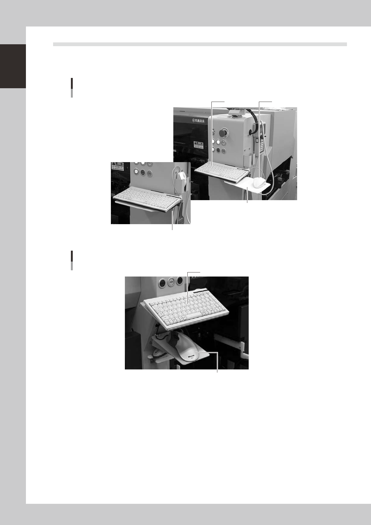
2.1 Keyboard and mouse
This machine is equipped with a keyboard and mouse (trackball for YG200L) as standard features to operate
the machine or edit data settings. To select a menu button or parameter item on the operation screen, click it
with the left mouse button.
Mouse and mouse pad can be retracted.
Keyboard and mouse
YG200
Keyboard Mouse
Mouse pad
23105-M2-00
Keyboard and trackball
YG200L
Keyboard
Trackball
23106-M2-00
1-7
1
Part names and functions
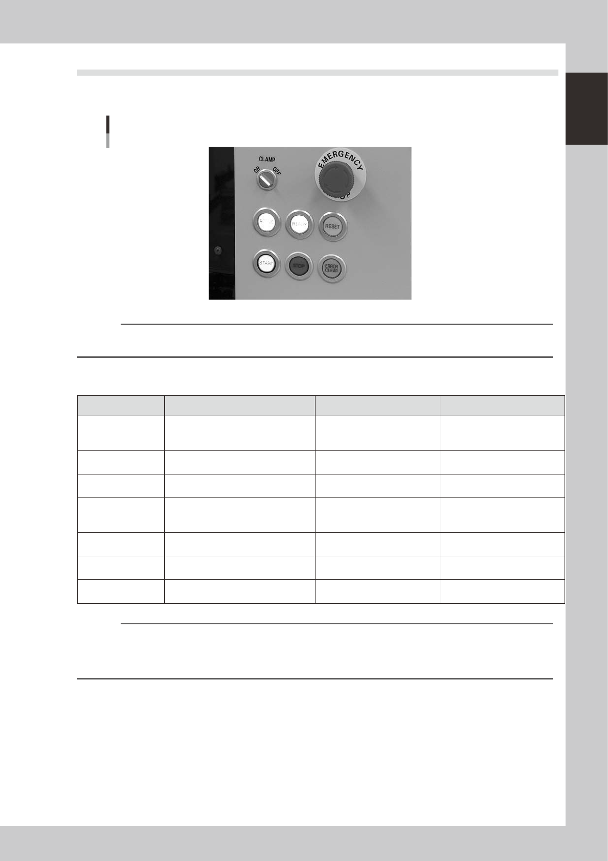
2.2 Operation panel buttons
The operation panel buttons are provided on the front and rear (option) of the machine to run major commands
frequently used to operate the machine. Each button is lit while turned on.
Operation panel buttons
23104-M2-00
Reference
The button positions slightly differ between the YG200 and YG200L. The operating methods and functions are the
same.
n
Operation panel button functions
Button name Use the button to: OFF ON
ACTIVE
Enable other keys. (The front and rear
[ACTIVE] keys cannot be turned on
simultaneously.)
• After machine has started.
• The other table has access
rights to operate machine.
• This table has access rights to
operate machine.
READY
Release emergency stop and turn the
servo on.
• SERVO OFF
(Motor power OFF)
• SERVO ON
(Motor power ON)
RESET
Stop automatic operation and return to
standby for board production.
• Machine is in normal operation
or stopped.
• Machine has been reset.
START
Perform component placement
according to board data.
• Machine is stopped.
• Machine is in normal operation.
[Flash]
Pause or step operation
STOP
Interrupt automatic operation. (Press
START to resume operation.)
• Machine is in normal operation. • Error occurred.
ERROR CLEAR
Stop buzzer sound and clear error
screen.
• Machine is in normal operation. • Error occurred.
EMERGENCY STOP
Trigger emergency stop. Turn to the
right to release it.
n
NOTE
The [ACTIVE] button is provided on both front and rear (option) panels, but cannot be turned on simultaneously. This
means that the [READY], [START], [ERROR CLEAR] and [RESET] buttons are enabled only when the [ACTIVE] key on the
same panel is turned on. (The [STOP] button can be used when the [ACTIVE] button is either on or off.)
The keyboard is enabled only when the [ACTIVE] key on the front panel is on.
1-8
1
Part names and functions
3. Head assembly
The head assembly is mounted on the XY arms and moves to pick up and place components. The following
sections describe the head assembly configurations and nozzle types.
3.1 Component pick-and-place head
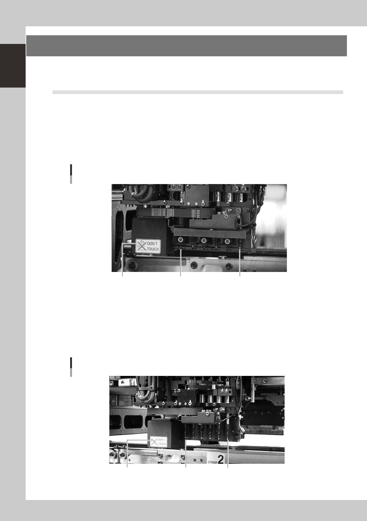
3.1.1 Six-in-line multi-head assembly (FNC type)
The FNC (flying nozzle change) type six-in-line multi-head assembly has 6 heads arranged in a row to pick up
and place components at high speeds. Head numbers are designated from 1 to 6, from the right as viewed from
the front of the head assembly. The spacing between adjacent nozzles attached to the head assembly is 16mm,
which is identical to the pitch of the feeder installation holes in the feeder plates.
Heads 2, 4 and 6 of the FNC type multi-head assembly have a flying nozzle changer (FNC) to change the
nozzle while the head assembly is moving to a component feeder.
Head 6
Heads 1, 3, 5 : Standard head
Heads 2, 4, 6 : FNC head
Head 1
Fiducial camera lighting unit
Six-in-line multi-head assembly (FNC type)
23107-M2-00
3.1.2 Six-in-line multi-head assembly (standard type)
As with the FNC type head assembly, this standard type six-in-line multi-head assembly has 6 heads arranged
in a row for component pickup and placement. Head numbers are designated from 1 to 6, from the right as
viewed from the front of the head assembly. The spacing of adjacent nozzles attached to the head assembly is
16mm, which is identical to the pitch of the feeder installation holes in the feeder plates.
Head 6 Head 1Fiducial camera lighting unit
Six-in-line multi-head assembly (standard type)
23108-M2-00