YG200_200L_E.pdf - 第38页
1-10 1 Part names and functions 4 . C o m p o n e n t s u p p l y s e c t i o n C o m p o n e n t s o r p a r t s a r e s u p p l i e d f r o m t a p e f e e d e r s i n s t a l l e d o n a f e e d e r p l a t e o r f r …
1-9
1
Part names and functions
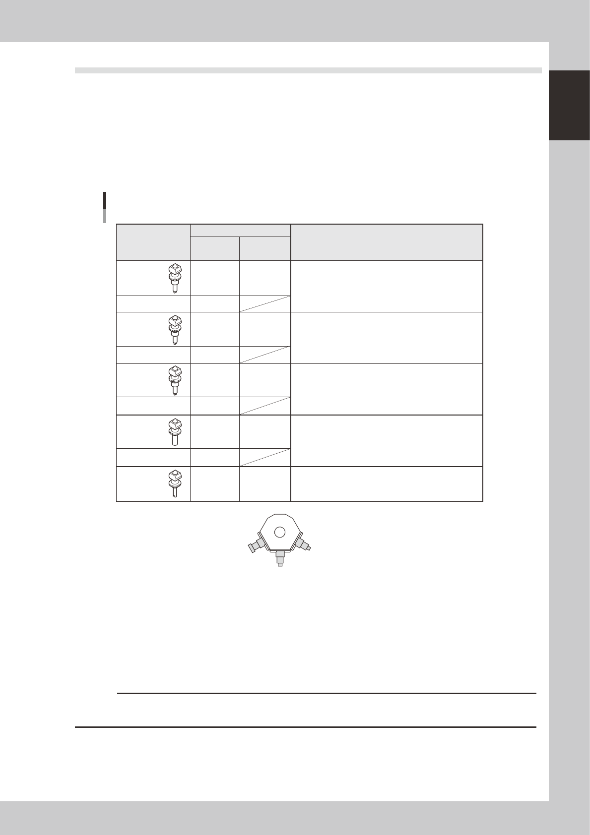
3.2 Nozzle types
To ensure stable component pickup, the correct nozzle that matches the component must be used. The
following sections explain typical nozzles which can be attached to each head.
3.2.1 Nozzles for the six-in-line multi-head assemblies
On the six-in-line FNC multi-head assembly, 5 types of nozzles Type A) can be chosen and attached to Heads
1, 3 and 5, while FNC nozzles (Type F) can be attached to Heads 2, 4 and 6.
On the six-in-line standard multi-head assembly, 5 types of nozzles (Type A) can be chosen and attached to
the mating heads (manual nozzle change).
Nozzle Type
Head No.
Typical Components
Type 201A
Type 201F
Type 202A
Type 202F
Type 209A
Type 209F
Type 203A
Type 203F
Type 206A
0603 to 1005 size chip components, mini-mold transistors, etc.
1608 to 3216 size chip components, mini-mold transistors, etc.
1608 to 3216 size chip components, mini-mold transistors, etc.
4532 to 7352 size components, 5 to 14mm SOP, etc.
Cylindrical chip (MELF) only
1, 3, 5
2, 4, 6
1, 3, 5
2, 4, 6
1, 3, 5
2, 4, 6
1, 3, 5
2, 4, 6
1, 3, 5
Six-in-line multi-head nozzles
Type 202 (209) F
Type 203F Type 201F
2
1
3
All heads
All heads
All heads
All heads
All heads
1 to 3: Index holder No.
View from the FNC gear side
Six-in-line
multi-head
FNC type
Six-in-line
multi-head
standard type
23109-M2-00
Type A nozzles
Type A nozzles (201A, 202 (209)A, 203A, and 204A) can be attached to all heads of six-in-line standard multi-head
assemblies or to Heads 1, 3 and 5 of six-in-line FNC multi-head assemblies.
Type F nozzles
The six-in-line FNC multi-head assemblies have a flying nozzle changer (FNC) at the tip of Heads 2, 4 and 6. Three types
of nozzles (Types 201F, 202F or 209F, and 203F) can be attached to each FNC head.
c
CAUTION
The above nozzles are specifically designed for use with the YG200 and YG200L surface mounters. Do not use them for
other machines.
1-10
1
Part names and functions
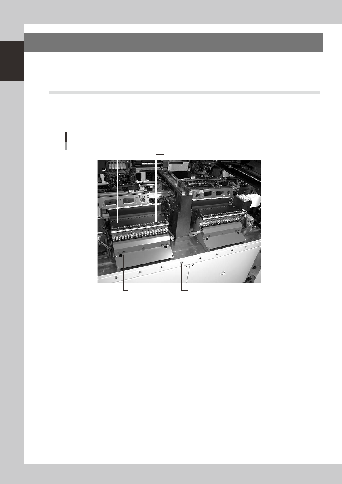
4. Component supply section
Components or parts are supplied from tape feeders installed on a feeder plate or from an external tray
changer or tray stacker. Under each feeder plate in the feeder setup section, power supply connectors and
air connectors are provided for driving optional units.
4.1 Supplying components from feeder plates
4.1.1 Fixed feeder plates
Tape feeders, bulk feeders and stick feeders are installed on the feeder plates, and operate by air supplied from
the mounter.
Feeder drive air outletFeeder plate
Power supply connector
Air connector
Feeder plate
Example of YG200
23110-M2-00
Power supply connector
When using optional units such as stick feeders, plug the power cord into this connector.
Air connector
When using optional units such as stick feeders and air gun, connect the air tube (O.D. 4mm) to this air connector. Air is
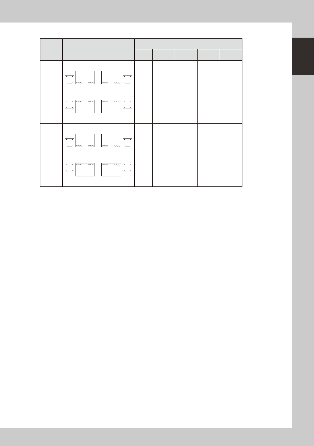
supplied from the mounter to the connected unit. The feeder plate layout and set numbers differ depending on the
machine specifications. Typical feeder plate layouts are shown below. Some feeders cannot be reached by a head
depending on the head assembly configuration and X-axis movement range. The tables below show feeder set numbers
that can be accessed by each head.
1-11
1
Part names and functions
n
Feeder plate layout
Type Layout
Set No.
Head
No.
A B C D
YG200
1
20
21
40
140
121
120
101
A B
CD
1 1 to 20 26 to 40
101 to 120 126 to 140
2 1 to 19 25 to 40
101
to
119
125 to 140
3 1 to 18 24 to 40
101 to 118 124 to 140
4 1 to 17 23 to 40
101 to 117 123 to 140
5 1 to 16 22 to 40
101 to 116 122 to 140
6 1 to 15 21 to 40
101 to 115 121 to 140
YG200L
1
24
25
48
148
125
124
101
A B
CD
1 1 to 24 28 to 48
101 to 124 128 to 148
2 1 to 24 27 to 48
101 to 124 127 to 148
3 1 to 24 26 to 48
101 to 124 126 to 148
4 1 to 23 25 to 48
101 to 123 125 to 148
5 1 to 22 25 to 48
101 to 122 125 to 148
6 1 to 21 25 to 48
101 to 121 125 to 148