YG200_200L_E.pdf - 第42页
1-14 1 Part names and functions 5 . C o n v e y o r u n i t a n d c o m p o n e n t r e c o g n i t i o n s y s t e m T h e c o n v e y o r u n i t u s e d t o c l a m p a b o a r d i n m o u n t i n g p o s i t i o n i …
1-13
1
Part names and functions
n
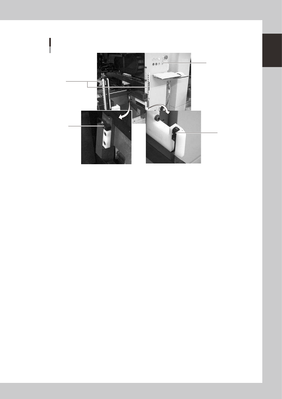
Mounter side
Switch and sensors on the mounter
3
1
2
4
23112-M2-00
1 Clamp ON/OFF switch
After installing the feeder exchange carriage into the mounter, turn this switch to the left (ON) to raise the feeder plate of
the feeder exchange carriage and automatically clamp it into the position. To unclamp, turn this switch to the right (OFF).
2 Forward end sensor
When the feeder exchange carriage is fully installed into the mounter, the green LED on this sensor lights up.
3 Area sensor for non-stop operation (option)
This safety area sensor is attached to mounters with a non-stop function. When the feeder exchange carriage is installed
into the mounter, the entrance sensors located at the front (or rear) of the mounter detect the feeder exchange carriage
and turn off this area sensor function.
4 Entrance sensor for non-stop feeder exchange carriage (option)
This sensor is attached to the front (or rear) of mounters with a non-stop function. When the feeder exchange carriage is
installed into the mounter, this sensor detects the feeder exchange carriage and turns off the area sensor function to
permit removing and installing the feeder exchange carriage even during automatic operation.
1-14
1
Part names and functions
5.
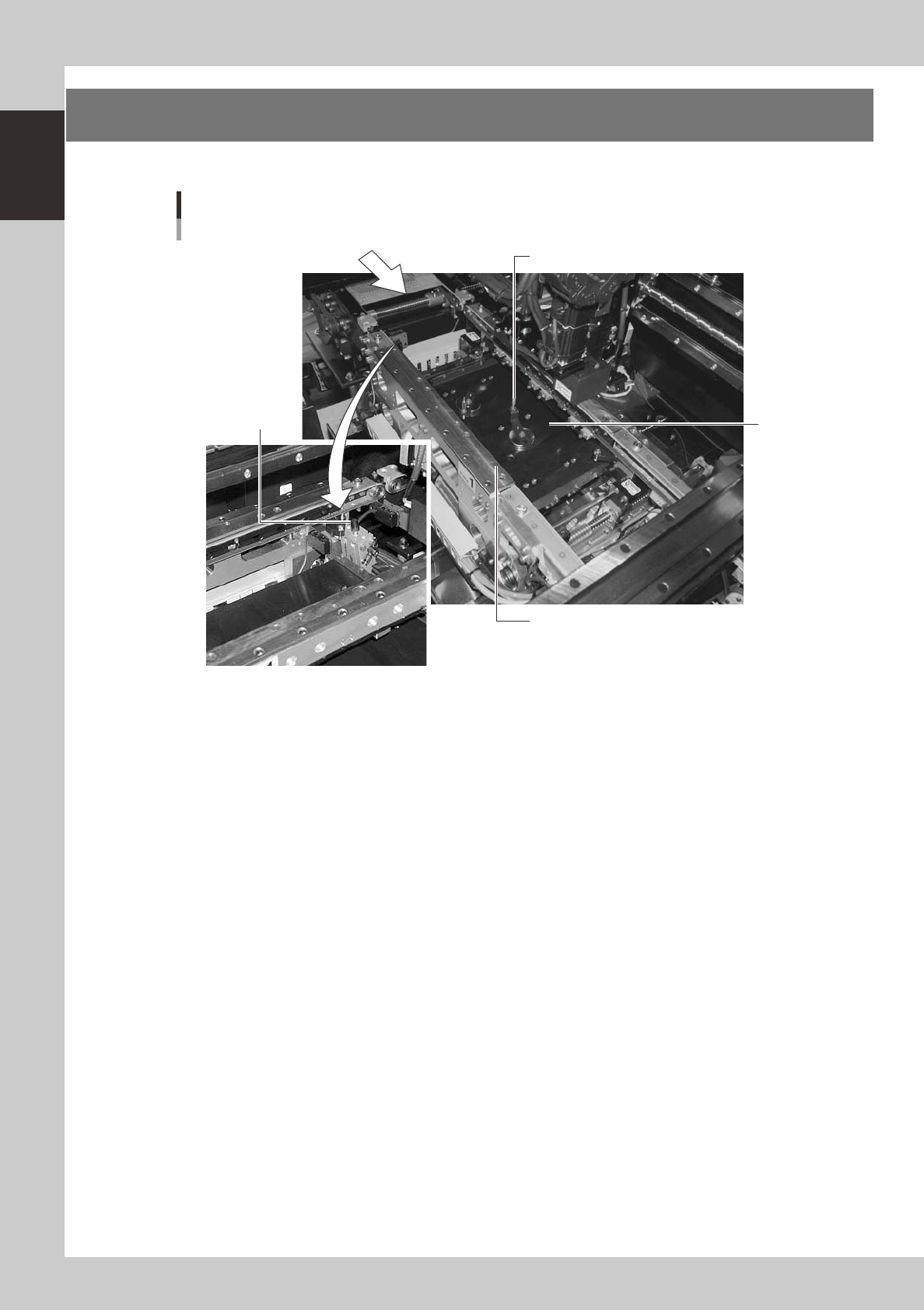
Conveyor unit and component recognition system
The conveyor unit used to clamp a board in mounting position is described below.
PCB
4
2
1
Conveyor units
3
23113-M2-00
1. Main stopper
When a board is carried in on the conveyor, the main stopper halts travel of the board in the component mounting
position. (Double stopper is optional.)
2. Push-up plate
The push-up plate clamps the board up against the conveyor rails, with the supporter pins attached by magnet on the
push-up plate.
3. Push-up pins
These pins are arranged on the push-up plate and secure the board by pushing it up from the bottom.
4. Board edge clamp unit
This unit clamps the board by pushing its edges up against the board hold plates.
1-15
1
Part names and functions
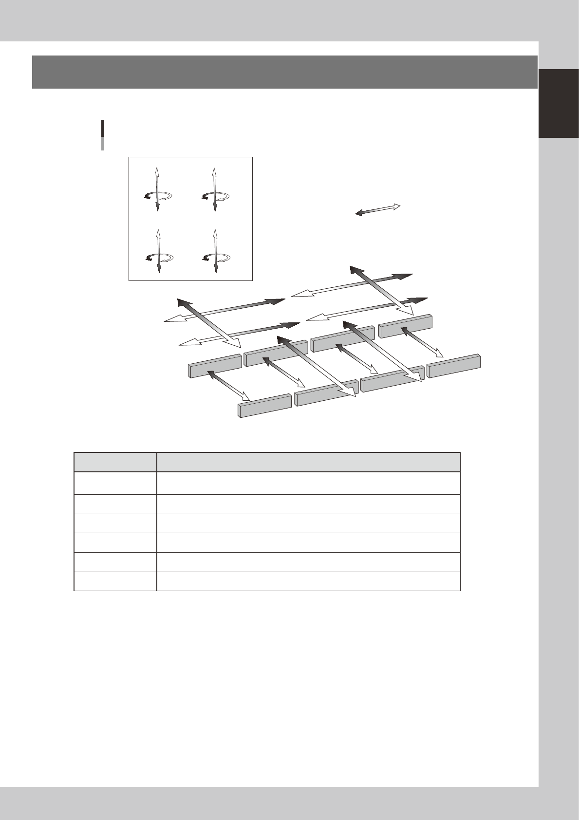
6. Axis configuration
The machine axis configuration and operation are shown in the drawing and table below.
Plus direction
Minus direction
Y1 axis
Y2 axis
X4 axis (D table)
X1 axis (A table)
X3 axis (C table)
X2 axis (B table)
YT1 axis
YT2 axis
W1 axis
W2 axis
W3 axis
W4 axis
Z4 axis
R4 axis
Z3 axis
R3 axis
Z1 axis
R1 axis
Z2 axis
R2 axis
Axis configuration
Head unit CHead unit D
Head unit BHead unit A
23114-M2-00
n
Function of each axis
Axis Function
X1, X2, X3, X4
Moves the head assembly above the conveyor table in parallel with the board flow
direction
Y1, Y2 Moves the head assembly perpendicular to the board flow direction.
YT1, YT2 Moves the conveyors (W2, W3) in the Y-axis direction.
Z1 to Z8 Controls the height of each component pick-and-place head.
R1, R2, R3, R4, Rotates the nozzle shafts of each head
W1, W2, W3, W4 Changes the conveyor width.