YG200_200L_E.pdf - 第47页
Chapter 2 Basic operation Contents 1 . B e f o r e o p e r a t i o n 2 - 1 1 . 1 C a n c e l i n g e m e r g e n c y s t o p 2 - 1 1 . 2 C l e a r i n g a n e r ro r 2 - 2 1 . 3 T y p i c a l e r r o r s a n d t r o u b …
1-18
1
Part names and functions
8. Other options
8.1 QFP dump station
The QFP dump station (hereafter called dump station) is a QFP recovery conveyor designed to attach to the
feeder plate of a YAMAHA surface mounter. If a QFP is judged defective by vision camera recognition, that
QFP is temporarily placed on this dump station without being damaged. The QFP placed on the dump station
is then conveyed back at a specified feed pitch. When the dump station becomes full, the memory counter or
overflow sensor detects it and displays an error message before the next defective QFP is returned to the dump
station.
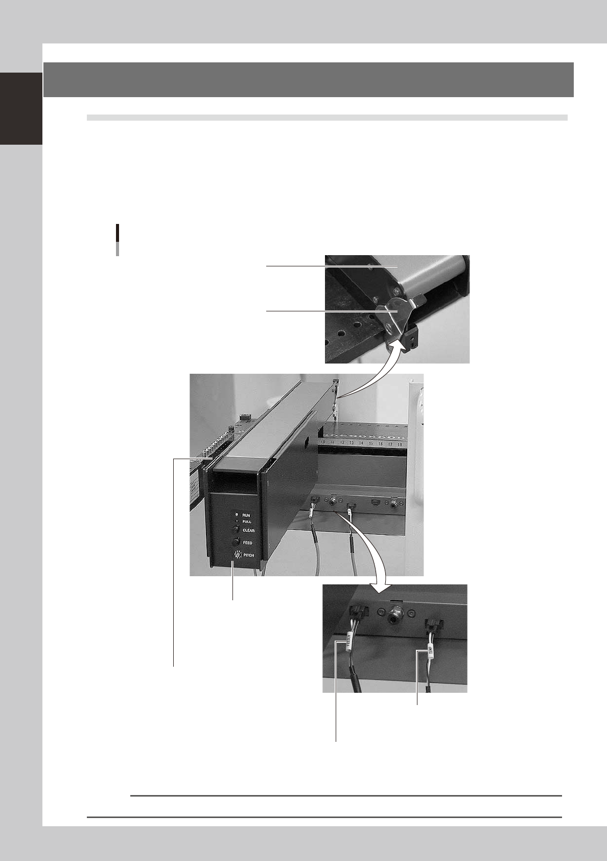
Photographs below show major parts and functions of the dump station.
Clamp lever
Use this lever to lock or unlock
the dump station to the feeder plate.
DUMP harness (signal cable)
Used to interface between the dump station
and the mounter for exchanging signals.
FEEDER harness (power supply cable)
Supplies power to the dump station from the mounter.
Manual operation panel
Use the switches on this operation panel
to set the feed pitch, move the belt at the
specified pitch and clear the count.
The LED lamps also show the
operation status.
Overflow sensor (option)
QFPs placed on the dump station
are carried back by the belt conveyor.
When a QFP arrives at the end of
the dump station, this overflow sensor
detects it and displays an error message.
Conveyor belt
Conveys QFPs placed on the
dump station at a specified feed pitch.
Major parts and functions
23117-M2-00
n
NOTE
For how to use the QFP dump station, refer to the option manual "QFP dump station".

Chapter 2 Basic operation
Contents
1. Before operation 2-1
1.1 Canceling emergency stop 2-1
1.2 Clearing an error 2-
2
1.3 Typical errors and troubleshooting 2-
3
2. Operation screen and buttons 2-8
2.1 Basic configuration of operation screen 2-8
2.2 Setup screen 2-1
0
2.3 Unit screen 2-1
1
3. Starting and stopping the machine 2-16
3.1 Pre-operation check 2-17
3.2 Starting the machine 2-1
8
3.3 Warming up the machine 2-2
0
3.4 Adjusting the conveyor unit setup 2-2
2
3.4.1 Conveyor unit setup flow 2-22
3.4.2 Conveyor width 2-23
3.4.3 Push-up pins 2-24
3.5 Preparing the component supply unit 2-25
3.5.1 Tape feeder 2-25
2-1
2
Basic operation
1. Before operation
The following explains how to cancel emergency stop and clear errors. Read before operating the machine.
n
Cautions during machine operation
• Do not turn off the compressed air during operation. The machine may malfunction, as pneumatic devices are not
correctly controlled.
• Before beginning maintenance work, always make sure that no air pressure remains in air cylinders.
n
Cautions during power outages
If a power outage (blackout) occurs during automatic machine operation, always turn the main power switch off to
prevent faulty operation after power has been restored.
1.1 Canceling emergency stop
Follow these steps to cancel emergency stop.
1
Release the emergency stop button.
When the emergency stop button is pressed, turn it clockwise to release it.
2
Check safety.
Before continuing the procedure, check the surrounding area for safety.
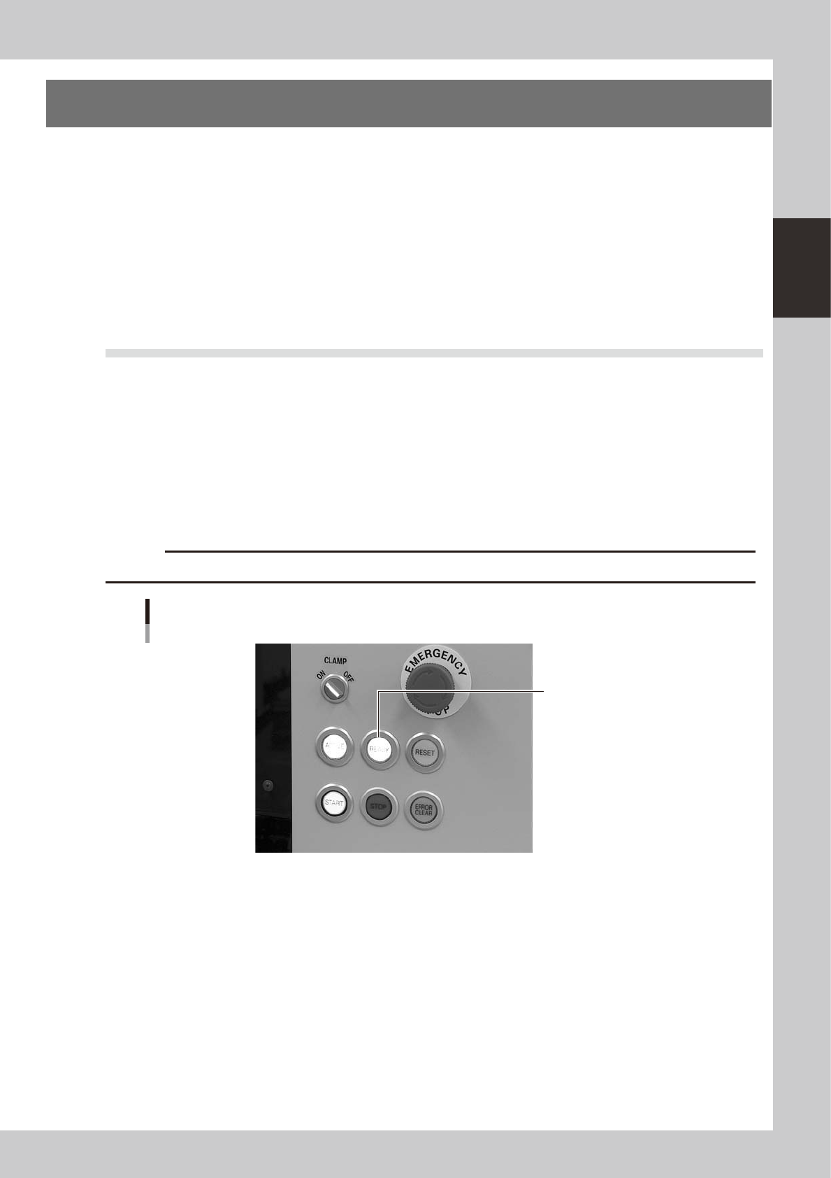
3
Press the [READY] button.
Pressing the [READY] button on the operation panel turns on the servomotors.
c
CAUTION
The [READY] button is enabled only when the [ACTIVE] button next to it is turned on.
[READY] button
Press the [READY] button
to turn on the servo.
23200-M2-00
4
Check the signal light and screen display.
Check that the red lamp of the signal light is off and the emergency stop sign the top left (status area)
of the operation screen is now off.