YG200_200L_E.pdf - 第59页
2-12 2 Basic operation B u t t o n n a m e F u n c t i o n 8 P u s h U p O p e n s t h e " C o n v e y o r P u s h U p " d i a l o g b o x . C h e c k o r e n t e r t h e b o a r d t h i c k n e s s a n d p r e…
2-11
2
Basic operation
2.3 Unit screen
This section describes the manual operation buttons on the Unit screen.
n
Manual conveyor operation
3
1
2 4
6
7 8
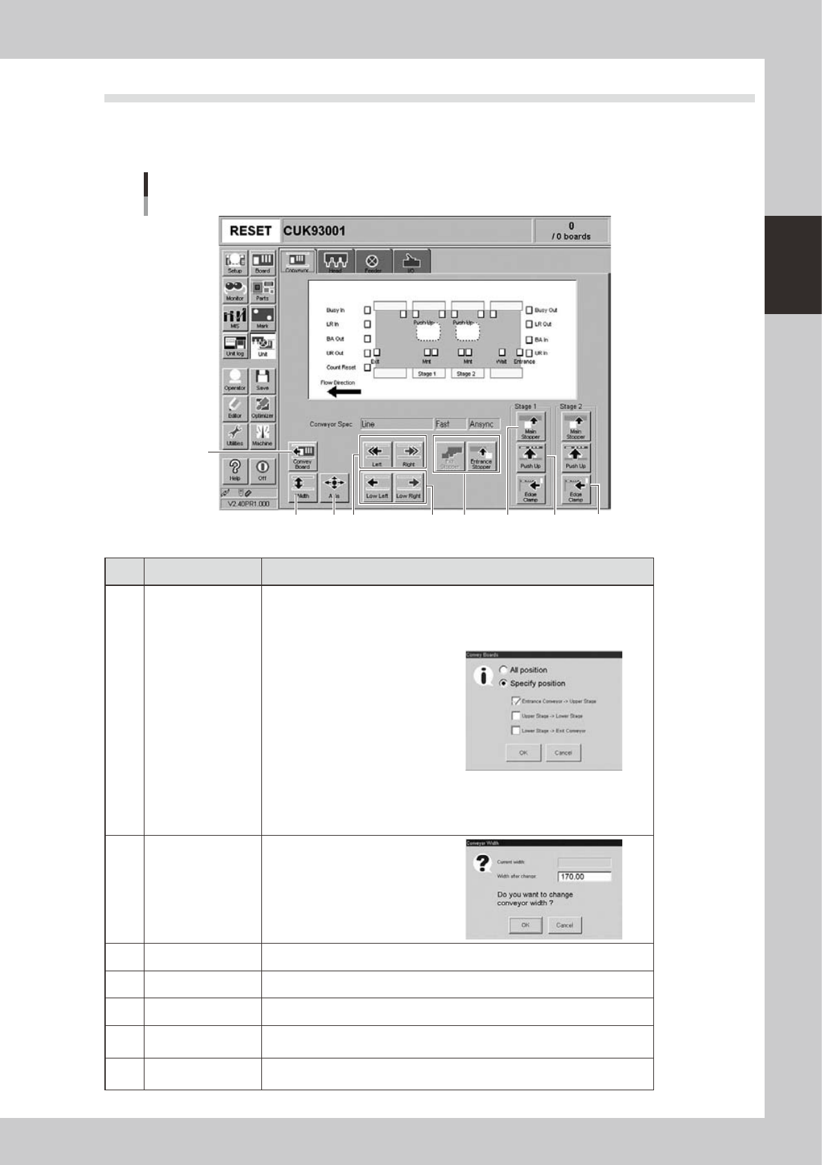
[Unit] - [Conveyor] screen
Screen example of YG200L
5
9
24204-M2-00
Button name Function
1 Convey Board
Opens the dialog box shown on
the right. Specify the method for
transferring boards, for example, from
the conveyor entrance or standby
position to the clamp position.
• "All positions": Transfers the boards
on the conveyor in sequence from
"Downstream stage to exit conveyor" -
"Upstream stage to downstream stage"
"Entrance conveyor to upstream
stage".
• "Specify position": Transfers the
boards only in the sections specified
with the check box under this button.
When all three check boxes are
selected, this is the same as selecting
the "All positions" option button
2
Width
Displays the "Conveyor Width" dialog
box. Check or enter the conveyor
width and press the [OK] button to
adjust the conveyor width.
3 Axis Opens the "Move Axis" screen that allows manual movement on each axis.
4 Left, Right Rotates the conveyor belt.
5 Low Left, Low Right Rotates the conveyor belt at a slow speed.
6
Exit Stopper / Entrance
Stopper
Raises or lowers the exit stopper or entrance stopper.
7 Main Stopper
Raises or lowers the main stopper that stops a board in the clamp position on
the conveyor.
2-12
2
Basic operation
Button name Function
8 Push Up
Opens the "Conveyor Push Up"
dialog box. Check or enter the board
thickness and press the [OK] button to
clamp the board by pushing it up from
the bottom.
9
Edge Clamp
(YG200L only)
Use this button to check the edge clamp operation.
n
Axis movement
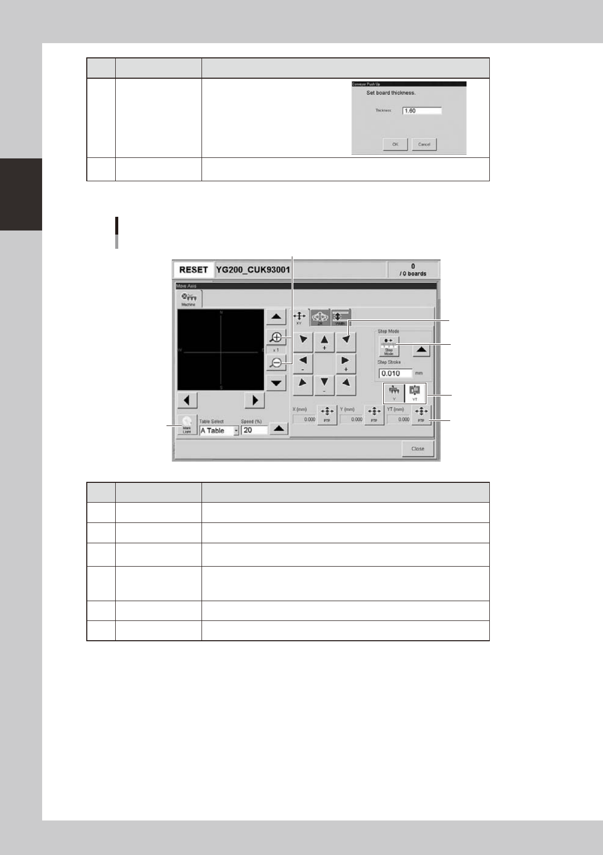
"Move Axis" screen
1
2
3
4
5
6
24206-M2-00
Button name Function
1 Zoom in/out (+, -) Zooms in or out the image. (16 times to 1/16 times)
2 Mark Light Allows changing mark lighting manually. Using this button does not affect data.
3 PTP
Displays the "PTP" dialog box that allows directly specifying the position where
you want to move the selected axis.
4 Step Mode
When this button is pushed in, the selected axis can be moved in "step mode
(inching mode)" with the arrow buttons at a specified step stroke (inching
stroke).
5 Arrow Use these buttons to move the selected axis in the desired direction.
6 Y/YT Use these buttons to switch between the Y axis and YT axis (table axis).
2-13
2
Basic operation
n
Manual head operation
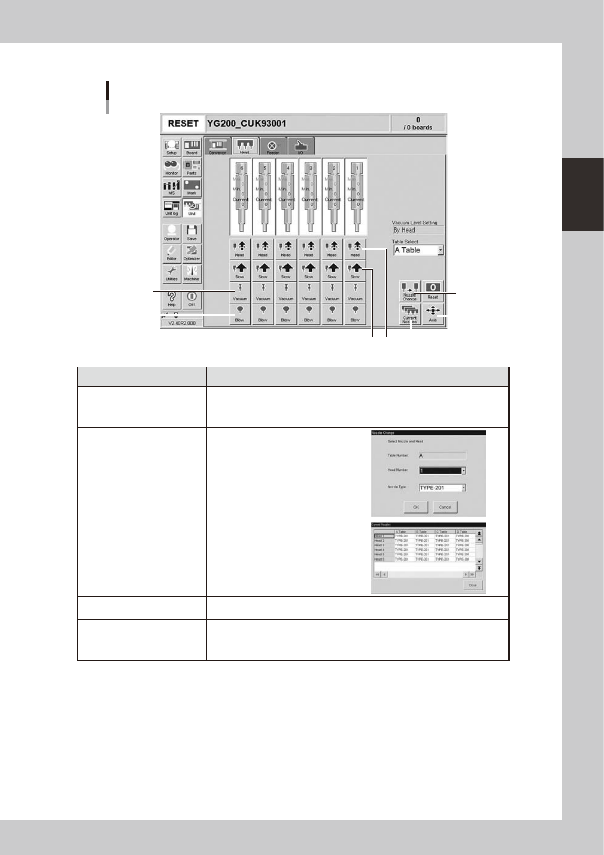
[Unit] – [Head] screen
1
2
3
5
476
24218-M0-00
Button name Function
1 Vacuum Turns the vacuum of each head on or off.
2 Blow Turns the air blow in each head on or off.
3 Nozzle Change
Opens the "Nozzle Change" dialog box.
Specify the head and nozzle type to
perform nozzle change.
4 Current Nozzles
Shows a list of nozzle types currently
attached to each head.
5 Axis
Opens the "Move Axis" screen. This is the same as the [Axis] button on the [Unit]-
[Conveyor] screen.
6 Slow Switches the head up/down speeds between "fast" and "slow".
7 Head Moves the heat up or down.