Operating manual vacuum pump 2SH_Eng.pdf - 第11页
Gardner Denver Elmo Technology GmbH 11 / 18 610.00139.40.000 Installation DANGER Electrical hazard! The electrical connection must be carried out by qualified and authorized el ectricians! DANGER Electrical hazard! Befor…
Gardner Denver Elmo Technology GmbH 10 / 18 610.00139.40.000
Installation
5.1 Installing the system
CAUTION
Risk of stumbling and falling!
Make sure that the system does not create po-
tential stumbling points!
If necessary barricade off the system with a
protective fence or mark it out with red-and-
white tape or similar.
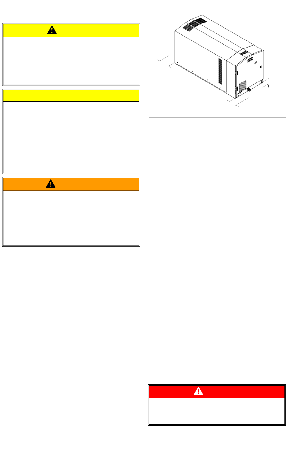
CAUTION
Risk of damaging the system through over-
heating!
The system is to be set up so that the discharge
of heat and the inflow of cool air are not hin-
dered. The minimum gap for heat dissipation
(
Fig. 4: Minimum gaps heat dissipation) is to be
maintained.
Outlet air from other machines and equipment
must not be directly sucked into the machine!
WARNING
Risk presented by system falling over or
falling down!
When setting up moveable machine parts or
when installing at a considerable height and
without any safety protection against falling then
the system must be secured to the surface it is
set up on.
Conditions for setting up the system:
Set up the system:
• on even, level surfaces,
• on stationary (fixed) surfaces or structures,
• at a height of a max. 1000 m [3280 ft] above
mean sea level.
When setting up at over 1,000 m [3280 ft]
above sea level, please check with the service
department first.
< 0,09 m
< 0,2 m
< 0,2 m
610.00139.99.B04
Fig. 4: Minimum gaps heat dissipation
When setting up the system the following points
are to be observed:
• The load-bearing capacity of the installation
surface must be designed to take the weight
of the system.
• The oscillatory response at the place of
installation must be taken into consideration.
The overall oscillations in the system depend
on the following factors:
-
the natural oscillations in the system,
-
the alignment and positioning,
-
The nature (oscillatory response) of the
bearing surfaces,
-
the effects resulting from oscillations in
other components and parts of the plant
(external oscillations).
The maximum permissible value for oscillations is
v
eff
= 4.5 mm/s [0.177"/s].
To ensure the system functions properly and has
a long service life, this value should not be ex-
ceeded.
As a rule this value can be kept to without the
need for a special type of foundation or a special
base plate.
For other details on the system's oscillatory re-
sponse, check with the service department.
• System using lockable wheels (pos.
11, pa-
ge
3) secure against to stop it rolling away.
5.2 Connecting the system to the electrical
supply
DANGER
Electrical hazard!
Incorrect actions can lead to severe harm to
persons and damage to objects!
Gardner Denver Elmo Technology GmbH 11 / 18 610.00139.40.000
Installation
DANGER
Electrical hazard!
The electrical connection must be carried out by
qualified and authorized electricians!
DANGER
Electrical hazard!
Before beginning any work on the system:
• De-energize it.
• Protect it from being switched on again.
• Make sure that it is de-energized.
• Earth it and bypass it.
• Cover or block off adjoining parts which are
still live.
DANGER
Electrical hazard!
Replace any loose connections and burnt and
scorched feed lines!
DANGER
Electrical hazard!
The system is to be installed in such a way that
external effects cannot lead to damage of the
electrical equipment.
Lay out electrical cables free of damage from
external influences and make sure they are not
under tension!
CAUTION
An incorrect electrical connection can severely
damage the system!
Regulations:
Set up the electrical connection:
• in accordance with the currently valid national,
local and plant-specific regulations and re-
quirements,
• in accordance with the regulations of the
power company.
Supply of electrical power:
The conditions at the place of use must agree
with the details on the data plate.
Permissible deviations which do not lead to loss
of performance:
• ±5% variation in voltage
• ±2% deviation in frequency
5.2.1 Connecting mains cable
DANGER
Danger from lethal leakage current
(PE) >3.5 mA to earth!
Set up connection as a permanent installation.
Set up double protective earth system.
Set up the electrical connection:
• as a permanent safe electrical connection.
• as permanent wiring with suitable cable sock-
ets.
• Connect the mains connecting cable (pos.
19,
page
4) in accordance with the following dia-
gram on the operator’s side of electrical cabi-
net:
Conductor Connection
Conductor 1 L1
Conductor 2 L2
Conductor 3 L3
Protective conductor
(green-yellow)
Terminal
• Ground (pos. 18, page 4) the earth connec-
tion.
WARNING
Electrical hazard!
Air gaps between naked, current-carrying parts
and between such parts and to ground:
5.5 mm [0.217"] (at a measured voltage of
U
N
≤ 690V)
Ends of wires must not stick out!
WARNING
Electrical hazard!
Connecting terminals must be free of
• foreign objects,
• dirt,
• moisture.
Close and seal the cable entry openings against
the entry of dust and water.
Check regularly to make sure they are sealed
tight.
Gardner Denver Elmo Technology GmbH 12 / 18 610.00139.40.000
Commissioning
5.2.2 Installing the EMERGENCY Stop
switch
• The EMERGENCY stop system must be
guaranteed via an external control unit.
• This control unit must prevent an auto-
matic re-starting of the system
5.2.3 Connecting the earth leakage current
breaker
DANGER
Danger from lethal electric shock!
In the case of a fault to frame a smooth DC
earth fault can block the release of an AC or
pulse current earth fault current breaker and
thus neutralize the protection system for all
components in the earth fault current breaker.
• Use a pulse current earth fault current
breaker in equipment containing driver regu-
lators with single phase mains connection
(L1/N).
• Use an earth fault current breaker suitable for
all types of currents in equipment with driver
regulators with three-phase mains connection
(L1/L2/L3).
• Install earth fault current between mains feed
and the driver regulator only.
• Earth fault current breakers can be acciden-
tally triggered by
-
capacitive equalizing currents from the ca-
ble shield when operating (especially with
long, shielded power cables),
-
connecting several driver regulators to the
mains at the same time,
-
using additional noise filters.
5.2.4 Connecting control line
Connect the control line plug from the equipment
to the control system (pos.
23, page 4).
Monitoring components are controlled in accor-
dance with operating specifications.
5.3 Mechanically connecting the system
CAUTION
When attaching hoses, make sure that these
are free from mechanical stresses.
Gases / vapours are sucked in via the suction
inlet (pos.
5, page 3) and discharged via the ex-
tracted air vent (pos.
9, page 3).
Remove the seal
The connection openings are sealed at delivery
in order to prevent ingress of foreign matter to the
intake connection (pos.
5, page 3).
Remove the seals immediately before connecting
up the hose system.
5.3.1 Connect the suction intake
Connect the suction line on the plant side to the
suction intake (pos.
5, page 3) and secure with
hose clip.
5.3.2 Cooling air vents
• Check cooling air vents (pos. 7, page 3) for
foreign objects and remove them.
The side cooling air vents can be closed while
operating under normal conditions.
5.3.3 Extracted air vent
The gases / vapours are discharged via the ex-
tracted air vent (pos.
9, page 3) into the sur-
roundings.
No assembly steps are needed here.
6 Commissioning
6.1 Preparing and starting up the system
The start-up procedure on commissioning the
system is the same as for operation of the sys-
tem.
6.2 Switching off the system
The procedure for switching off the system on
commissioning it is the same as for operation of
the system.