Operating manual vacuum pump 2SH_Eng.pdf - 第3页
Gardner Denver Elmo Technology GmbH 3 / 18 610.00139.40.000 System design 1 System design 1 1 2 3 4 5 6 7 8 9 10 11 610.00139.99.B01 Fig. 1: System design 1 Status indicator lights “Pum p in oper ation”. 6 Rating plate 2…

© Gardner Denver Elmo Technology GmbH 2006
Disclosure, replication, distribution and / or editing of this document and the use and distribution of its content is prohibited
if not explicitly permitted. Violation obligates compensation.
All rights reserved in case of the issue of a patent, utility patent or design patent.
ContentsSafety
Contents
System design 1 .......................................................................................................................................3
System design 2 .......................................................................................................................................4
1
Safety ..................................................................................................................................................5
1.1
Definitions .................................................................................................................................5
1.1.1
Warning symbol............................................................................................................5
1.1.2
Key word ......................................................................................................................5
1.2
General safety instructions .......................................................................................................5
1.2.1
Other risks ....................................................................................................................6
2
Correct Use Of The Equipment ...........................................................................................................7
3
Technical Data ....................................................................................................................................8
3.1
Mechanical Data .......................................................................................................................8
3.2
Electrical data............................................................................................................................8
3.3
Operating conditions, normal operation ....................................................................................8
4
Transport .............................................................................................................................................9
5
Installation ...........................................................................................................................................9
5.1
Installing the system................................................................................................................10
5.2
Connecting the system to the electrical supply.......................................................................10
5.2.1
Connecting mains cable .............................................................................................11
5.2.2
Installing the EMERGENCY Stop switch ...................................................................12
5.2.3
Connecting the earth leakage current breaker...........................................................12
5.2.4
Connecting control line...............................................................................................12
5.3
Mechanically connecting the system ......................................................................................12
5.3.1
Connect the suction intake.........................................................................................12
5.3.2
Cooling air vents.........................................................................................................12
5.3.3
Extracted air vent .......................................................................................................12
6
Commissioning..................................................................................................................................12
6.1
Preparing and starting up the system .....................................................................................12
6.2
Switching off the system .........................................................................................................12
7
Operation...........................................................................................................................................13
7.1
Starting up the system ............................................................................................................13
7.2
Switching off the system .........................................................................................................13
7.3
System in normal operation ....................................................................................................13
8
Decommissioning the machine and shutting it down for a longer period of time..............................14
8.1
Storage conditions ..................................................................................................................14
8.2
Commissioning after a long shutdown period .........................................................................14
9
Maintenance......................................................................................................................................14
9.1
System maintenance...............................................................................................................16
9.2
Correcting faults ......................................................................................................................16
9.3
Service / Customer Service.....................................................................................................17
10
Disposal.............................................................................................................................................17
11
EC Declaration of Conformity............................................................................................................18
Gardner Denver Elmo Technology GmbH 3 / 18 610.00139.40.000
System design 1
System design 1
1
2
3
4
5
6
7
8
9
10
11
610.00139.99.B01
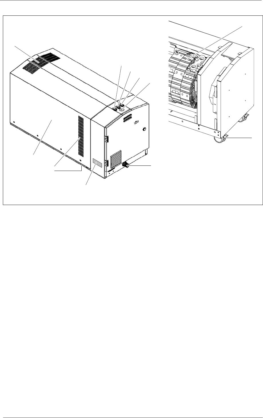
Fig. 1: System design
1 Status indicator lights “Pump in operation”. 6 Rating plate
2 Status indicator lights “Ready for operation”. 7 Cooling air vents
3 Status indicator lights “Converter failure” 8 Housing
4 Pressure gauge 9 Extracted air vent
5 Inlet flange 10 Unit
11 Lockable wheels
Gardner Denver Elmo Technology GmbH 4 / 18 610.00139.40.000
System design 2
System design 2
14
12
23 202224
13
15
21
18
19
17
16
610.00139.99.B02
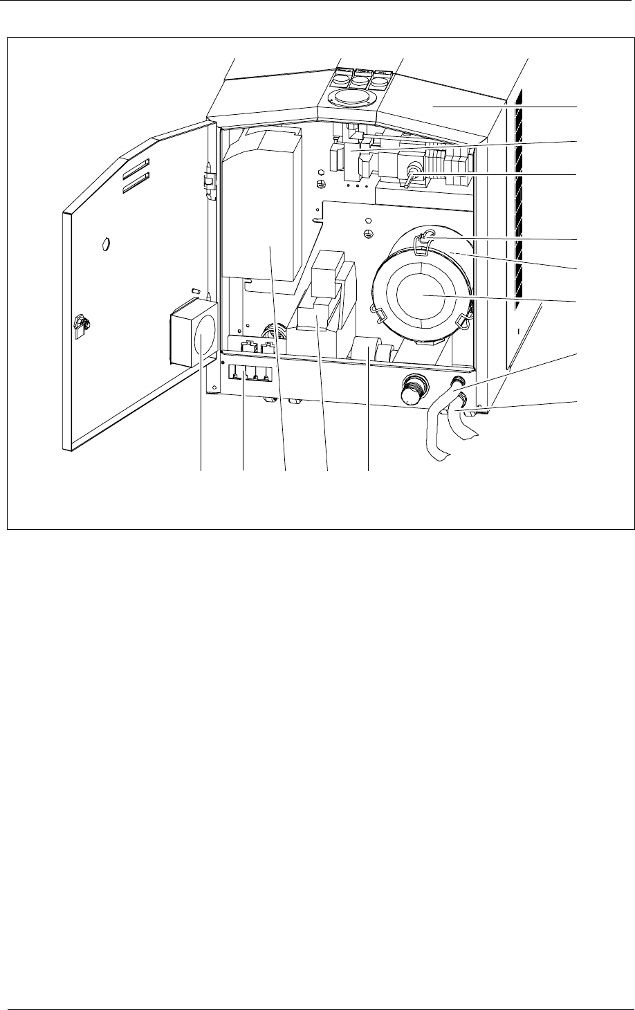
Fig. 2: System design
12 E-Module 19 Mains cable
13 Power supply 20 Vacuum relief valve
14 Main switch 21 Mains choke
15 In-line filter catch 22 Frequency inverter
16 Filter refill 23 Cable feedthrough for control line
17 Inline filter 24 Fan E-Module
18 Grounding cable