Operating manual vacuum pump 2SH_Eng.pdf - 第8页
Gardner Denver Elmo Technology GmbH 8 / 18 610.00139.40.000 Technical Data 3 Technical Data 3.1 Mechanical Data Dimensions Dimensions (width x height x depth) ca. [mm] ca. [inches] 1135 x 635 x 495 44,7 x 25,0 x 19,5 Mas…

Gardner Denver Elmo Technology GmbH 7 / 18 610.00139.40.000
Correct Use Of The Equipment
2 Correct Use Of The Equipment
This instruction manual
• applies for vacuum pump systems in the 2SH
series, type 2SH7 530.
• is complemented by the instruction manual for
the G_400e Liquid-Ring Vacuum Pump.
• contains instructions on transport, installation,
commissioning, operation, decommissioning,
storage, maintenance and disposal of the
2SH.
• must have been read and properly understood
2SH by operating and maintenance staff be-
fore beginning any work.
• must be complied with.
• must be available at the 2SH location.
The operating and maintenance staff for the 2SH
must be trained in the work to be carried out and
authorised to do so.
Work on electrical equipment must only be car-
ried out by a qualified electrician.
The 2SH
• is a system for the creation of a vacuum.
• consists of:
-
a housing with wheels (pos. 8, page 3)
-
a liquid ring vacuum pumps in the G_400e
series, type 2BH7 (pos.
10, page 3) (re-
ferred to below as the “unit“).
-
a vacuum shut-off valve (pos. 20, page 4).
-
an E-modulus with frequency converter
(pos.
12, page 4)
-
an in-line filter (pos. 17, page 4)
-
a pressure gauge (pos. 4, page 3)
-
and status indicator lights (pos. 1-3, pa-
ge
3).
• is used to extract, transport and condense the
following gases / vapours:
-
all dry and damp gases which are not ex-
plosive, combustible, aggressive or poi-
sonous,
-
preferably air or air-vapour mixtures.
-
for gases / vapours other than these,
please check with the service department.
• which, during operation, releases gases into
the environment with the following character-
istics:
-
outlet temperature max. 85°C,
-
outlet pressure ≈ ambient pressure,
-
clean and free of dust.
• is designed for industrial plant.
• is designed for continuous operation.
-
if it is switched on very frequently (at equal
intervals, about 5 times an hour) or there
are excessive gas inlet and ambient tem-
peratures, the tolerable coil and storage
temperatures could be exceeded.
-
consultation with the manufacturer is es-
sential for such operational conditions.
When operating the 2SH the limiting values listed
in chapter
3 Technical Data, page 8 ff are to be
complied with.
Foreseeable Misuse
The following are forbidden:
• use of the 2SH in non-industrial plant, unless
the necessary precautions and protective
measures have been taken at the plant, e.g.
protection against contact by children's' fin-
gers.
• use in areas in which explosive gases may
become present.
• the extraction, transport and condensing
of explosive, combustible, aggressive or poi-
sonous media.
• operation of the 2SH at any values other than
those given in chapter
3 Technical Data, page
8 ff.
For reasons of safety2SH it is forbidden to make
any changes to the .
The unit must not be either dismantled or disas-
sembled!
The Operator is allowed to carry out maintenance
and repair work to the extent described in this
instruction manual.
Maintenance and repair work which goes beyond
this to should only be carried out by companies
which have been authorised by the manufacturer
(ask the service department for details).
Gardner Denver Elmo Technology GmbH 8 / 18 610.00139.40.000
Technical Data
3 Technical Data
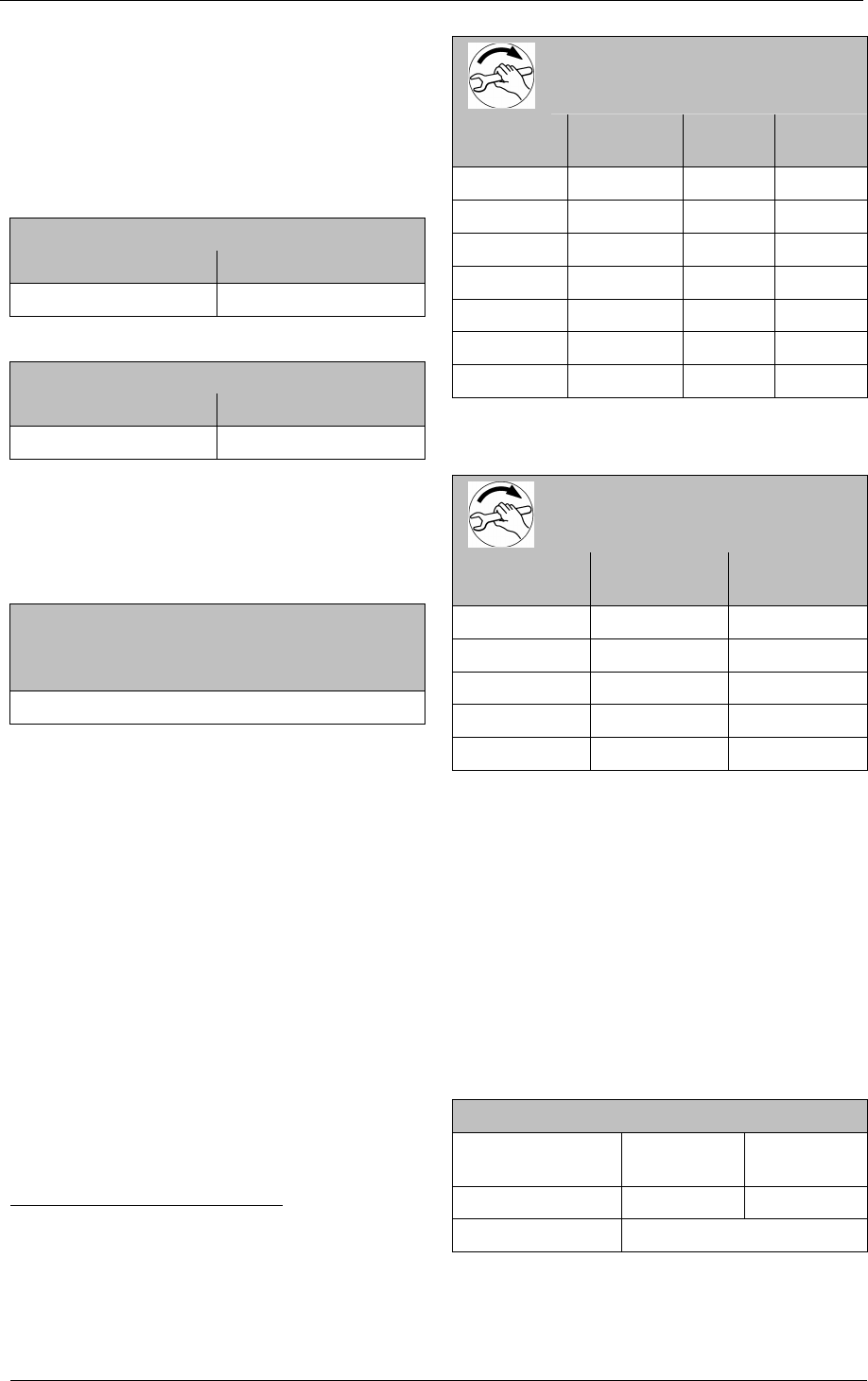
3.1 Mechanical Data
Dimensions
Dimensions (width x height x depth)
ca. [mm] ca. [inches]
1135 x 635 x 495 44,7 x 25,0 x 19,5
Mass / Weight
Weight
ca. [kg] ca. [lbs]
160 353
Minimum gaps for heat dissipation
The minimum gap for heat dissipation (all direc-
tions) is ≥ 0,5 m / ≥ 1.64 ft.
Noise level
1-m-measured area sound pressure level L
[dB (A)]
1
at 70 Hz:
63
Operating speed
See power rating plate on the housing (pos.
6,
page
3).
Tightening torques
The values given for tightening torque apply whe-
re no other details are available.
1
Measured area sound pressure level in accor-
dance with DIN 45635, T13, measured from 1 m
[3,28 ft] distance with Δp 600 mbar limiting and
cable connected to suction side, tolerance
± 3 dB (A).
Tightening torques
for screwed connections
(general)
Thread Strength
class
[Nm]
± 10 %
[ft lbs]
± 10 %
M4 5.6 1,4 1,03
M5 5.6 3 2,21
M6 8.8 8 5,90
M8 8.8 20 14,8
M10 8.8 40 29,5
M12 8.8 70 51,6
M16 5.6 100 73,8
(These values apply to all screwed connections
with the exception of electrical connections).
Tightening torques
for electrical connections
(terminal board connections)
Thread [Nm]
± 10 %
[ft lbs]
± 10 %
M4 1,0 0,738
M5 2,2 1,62
M6 3 2,21
M8 7 5,16
M10 11 8,11
(These values apply to all terminal board connec-
tions with the exception of terminal strips).
3.2 Electrical data
See power rating plate on the housing (pos.
6,
page
3).
The unit operates on a set frequency of 60 Hz.
Consultation with the service department is nec-
essary to change the frequency.
3.3 Operating conditions, normal operation
Standard conditions
Ambient tempera-
ture
+20°C +20.00°C
ambient pressure 101.3 kPa 14.7 psi
Humidity 50 %
Gardner Denver Elmo Technology GmbH 9 / 18 610.00139.40.000
Transport
Temperatures
Temperatures of the gases / vapours
intake temperature max. +40°C max. + 32°F
outlet temperature max. 85°C
Maximum permissible ambient temperature
max. +40°C max. + 32°F
min. +10°C min. + 32°F
Pressures
Intake pressure
Δpmax. 60 kPa max. ,0 psi
The system must not be connected on the pres-
sure side!
Outlet pressure
ca. 101.3 kPa ca. ,0 psi
≈ambient pressure
4 Transport
WARNING
Improper handling of the system can result
in serious or fatal injuries!
Have you read the safety notes in chapter
1
Safety, page 5 f.?
If not then you are not allowed to carry out any
work on or with the system!
WARNING
Hazard presented by tilting or falling loads!
Before transport make sure that all the compo-
nents are securely assembled and that all the
components for which the securings have been
loosened are either properly secured or re-
moved!
We recommend that a forklift or elevating-
platform truck be used for the transport.
Transport with lifting gear:
WARNING
Hazard presented by tilting or falling loads!
The following basic rules should be observed
when transporting with the aid of lifting gear:
• Use suitable load-handling devices (e.g. belts
or wires) and means of conveyance (e.g.
forklift truck, elevating-platform truck, crane).
• The load-bearing capacity of the lift gear and
load-handling devices must correspond to the
Mass / Weight of the system (page 8).
• Secure the system so that it cannot tilt over
or fall off.
• Do not stand under suspended loads!
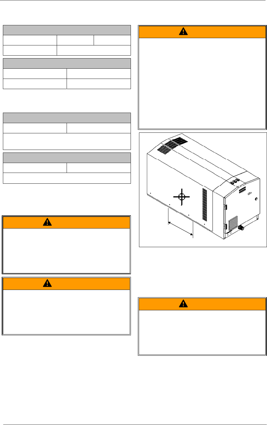
610.00139.99.B03
Fig. 3: Estimate the position of the centre of gravity
of the system.
ca.
5 Installation
WARNING
Improper handling of the system can result
in serious or fatal injuries!
Have you read the safety notes in chapter
1
Safety, page 5 f.?
If not then you are not allowed to carry out any
work on or with the system!