00198146-01_AI_120V_TX12_de_en - 第50页
3 Installation 3.1 Performing Preparatory Work Assembly Instructions / Montageanleitung SIPLACE TX Series Option 120 V 04/2017 50 Fig.6: Cable in machine frame ► Remove the two screws (2) fastening the cover (1) and rem…
Assembly Instructions / Montageanleitung SIPLACE TX Series
Option 120 V 04/2017
3 Installation
3.1 Performing Preparatory Work
49
3 Installation
3.1 Performing Preparatory Work
► Switch off the machine, disconnect it from the power supply and secure it to prevent
unauthorized reactivation. Observe the instructions in section 1.2 "Preparatory Work..." [}41].
DANGER
Checking for absence of voltage!
► Before you start working check the power supply for absence of voltage and observe
the waiting times! For more information about this read section 4.1.2 "Checking For
Absence of Voltage" [}58].
► Move the component trolley at location 2 out of the machine.
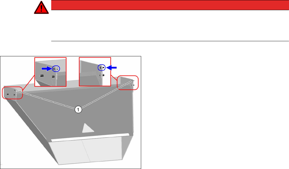
Fig.5: Waste tape chute
► Loosen the two safety screws(1) on the waste
tape chute and unhook the waste tape chute.
3 Installation
3.1 Performing Preparatory Work
Assembly Instructions / Montageanleitung SIPLACE TX Series
Option 120 V 04/2017
50
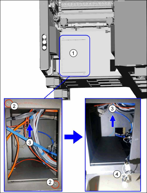
Fig.6: Cable in machine frame
► Remove the two screws (2) fastening the cover
(1) and remove the cover.
► Search the machine frame for the W3.1cable (4)
[03116403‑xx].
This cable has a bridging plug and is provided
with a sign for operating the machine with a va-
cuum pump.
Slightly pull this cable out of the machine.
► Use the cable ties (L=360mm) to tie all cables
and pneumatic lines(3) up high, so that they do
not touch the transformer later on.
Assembly Instructions / Montageanleitung SIPLACE TX Series
Option 120 V 04/2017
3 Installation
3.2 Installing the Transformer
51
3.2 Installing the Transformer
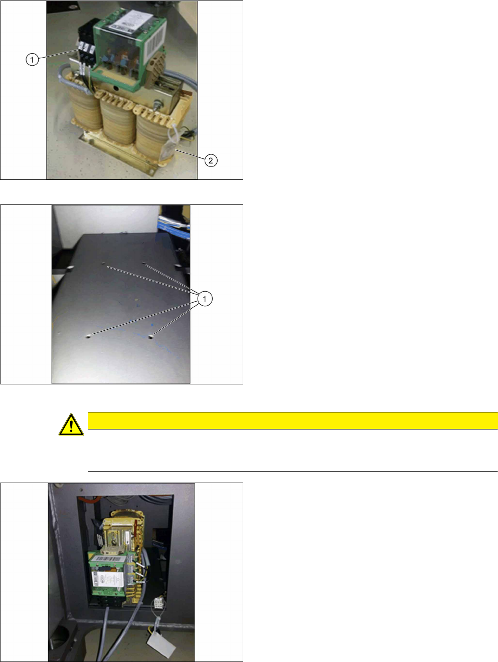
Fig.7: Transformer
The three phases of the output voltage at the trans-
former are secured by means of three safety fuses(1).
In addition, the transformer is provided with three
spare fuses(2).
► Remove the three spare fuses and keep them for
future use.
Fig.8: Transformer screw points
1. Screw points for the transformer
CAUTION
Do not damage the cables
► Make sure you do not damage the tied-up cables and hoses when performing the fol-
lowing steps.
Fig.9: Inserting the transformer
► Observe the orientation of the transformer. The
cables must reach out to the front of the opening.
► Tilt the transformer to the side and place it care-
fully into the machine.