00198146-01_AI_120V_TX12_de_en - 第52页
3 Installation 3.2 Installing the Transformer Assembly Instructions / Montageanleitung SIPLACE TX Series Option 120 V 04/2017 52 Fig.10: Transformer in the machine ► Place the transformer in the upright position in the …
Assembly Instructions / Montageanleitung SIPLACE TX Series
Option 120 V 04/2017
3 Installation
3.2 Installing the Transformer
51
3.2 Installing the Transformer
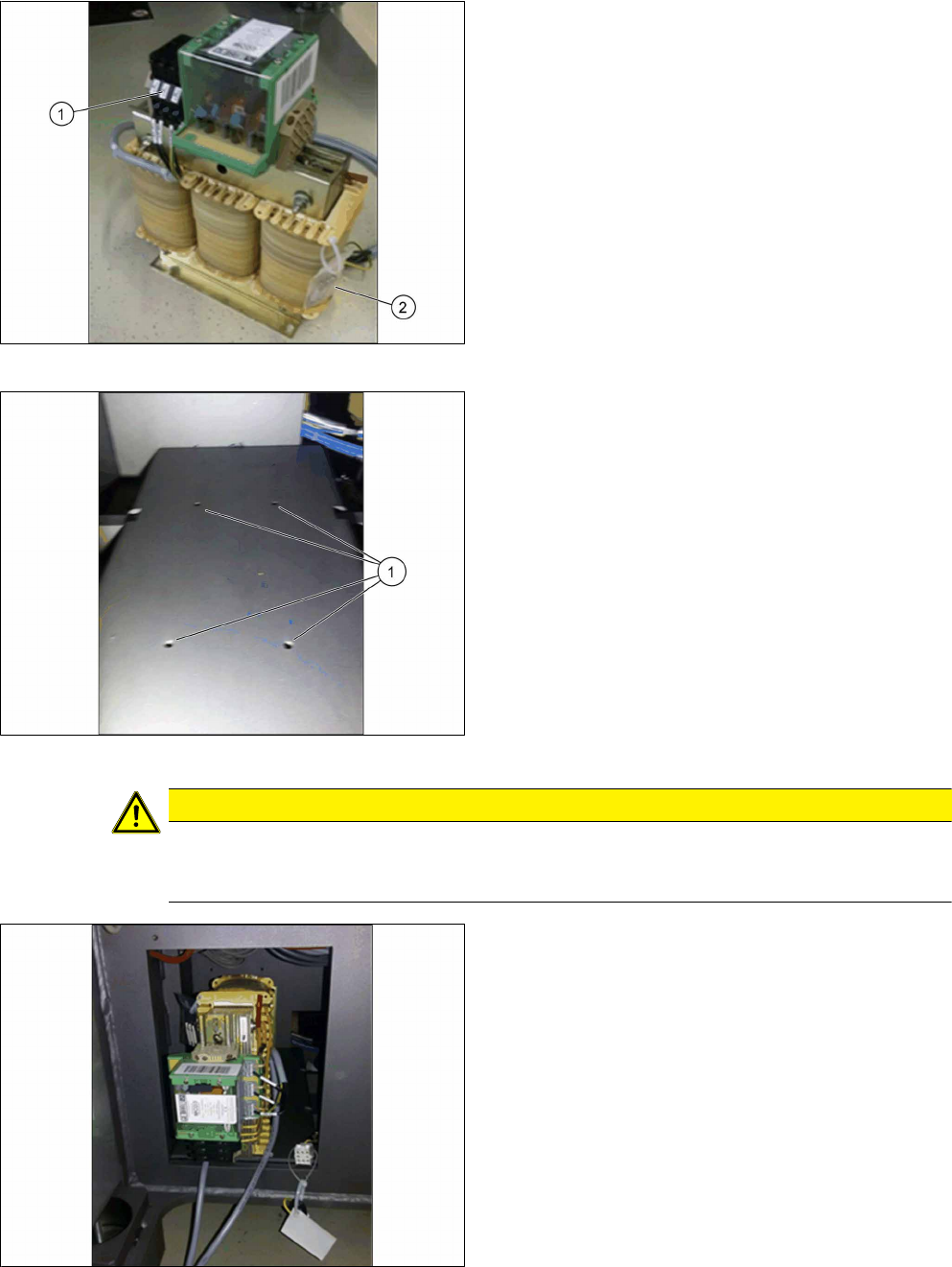
Fig.7: Transformer
The three phases of the output voltage at the trans-
former are secured by means of three safety fuses(1).
In addition, the transformer is provided with three
spare fuses(2).
► Remove the three spare fuses and keep them for
future use.
Fig.8: Transformer screw points
1. Screw points for the transformer
CAUTION
Do not damage the cables
► Make sure you do not damage the tied-up cables and hoses when performing the fol-
lowing steps.
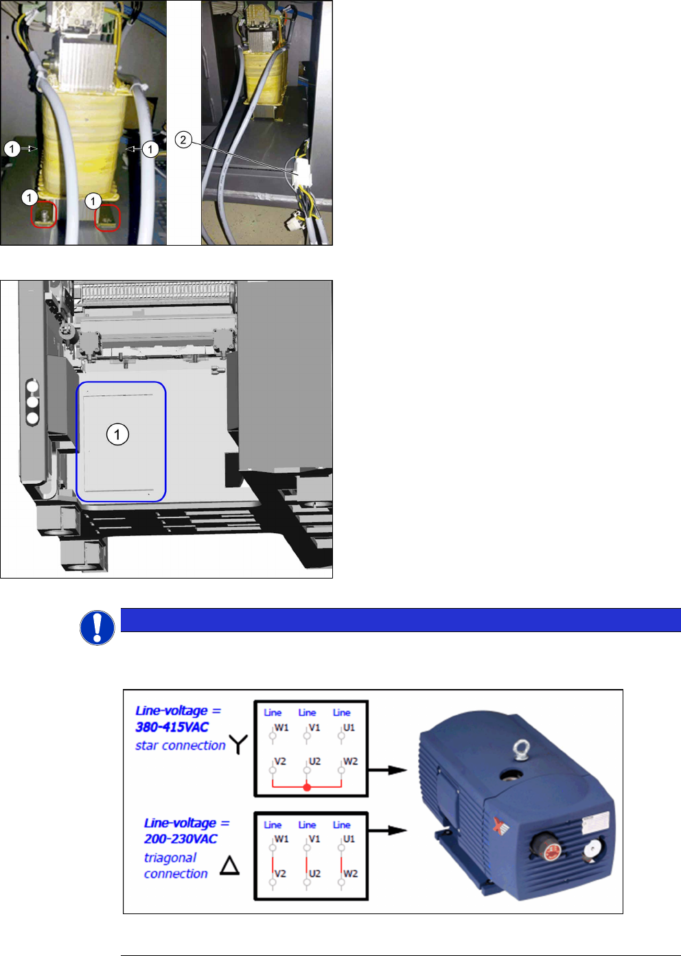
Fig.9: Inserting the transformer
► Observe the orientation of the transformer. The
cables must reach out to the front of the opening.
► Tilt the transformer to the side and place it care-
fully into the machine.
3 Installation
3.2 Installing the Transformer
Assembly Instructions / Montageanleitung SIPLACE TX Series
Option 120 V 04/2017
52
Fig.10: Transformer in the machine
► Place the transformer in the upright position in
the machine.
► Fasten the transformer with four M6x12 screws
and four lock washers (1).
► Unplug the bridging plug fitted on the cable(2).
Leave the bridging plug on the cable for a later
retrofitting.
► Plug in the transformer cable.
► Stow the cable in the machine.
Fig.11: Cover
► Mount the cover(1) using two fastening screws.
NOTICE
120V
On machines which use the 120 Voption, the vacuum pump must be set from the star to
the triangle.
A corresponding note is attached directly to the cable which is connected to the transformer
in the machine.
Assembly Instructions / Montageanleitung SIPLACE TX Series
Option 120 V 04/2017
3 Installation
3.3 Exchanging the circuit breaker
53
3.3 Exchanging the circuit breaker
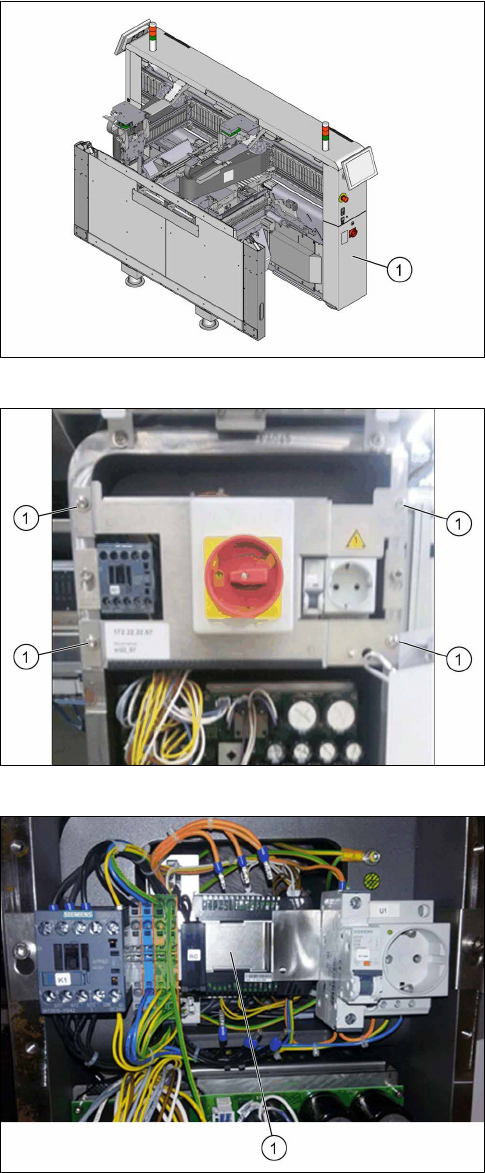
Fig.12: Power supply
► Open the door(1) to the power supply.
Fig.13: Main switch unit
► Remove the four fastening screws(1) from the
main switch unit.
Fig.14: Circuit breaker [03125553‑xx]
► Dismount the circuit breaker "3RV2 3-pole
4.5‑6.3A" [03125553‑xx].