00198146-01_AI_120V_TX12_de_en - 第60页
4 Appendix 4.1 Excerpts from the Service Manual Assembly Instructions / Montageanleitung SIPLACE TX Series Option 120 V 04/2017 60 Procedure for Determining Absence of Voltage Ensure a correct handling of the voltage tes…
Assembly Instructions / Montageanleitung SIPLACE TX Series
Option 120 V 04/2017
4 Appendix
4.1 Excerpts from the Service Manual
59
Execution / Working procedure:
●
The absence of voltage must be determined as closely as possible at the workplace, at all
pins, by a certified electrician or instructed electrical officer.
●
Make sure to select the correct measurement area or workplace.
●
Only touch the measuring device by the insulated test handles (up to inside handles). Do not
touch the test electrodes (testing tips).
●
During testing, take hold of the voltage tester fully (DUSPOL). Press the testing tips manually
against the part to be measured e.g. FLUKE T150 or T5-1000.
●
The contact electrodes or testing tips of voltage testers must always have a conductive elec-
trical contact with the system part to be tested.
●
The testing tips must always be securely clamped or plugged into the part to be measured.
Measuring lines must be well connected to the phase tester.
●
Ensure a secured and concentrated attachment and removal of the measuring device tips or
testing pins.
●
Use auxiliary clamps (banana plugs, crocodile clips, spider legs, measuring jacks) with suit-
able voltage and clamping reliability.
●
Read the measurement rotary field display at eye level and with no inhibited view. Watch out
for reflections and mirroring on measurement scale.
Measuring Device for Determining Absence of Voltage
DANGER
Only use the DUSPOL voltage tester!
Universal or multiple measuring devices for determining the absence of voltage are not ap-
proved.
The reason for this is that the correct voltage type (DC or AC) and the correct voltage range
need to be set in advance.
The direct current to be measured: 300VDC can cause serious or lethal injuries if the
measuring device is incorrectly set or defective.
► For this reason, only use the two-pin voltage tester (DUSPOL)!
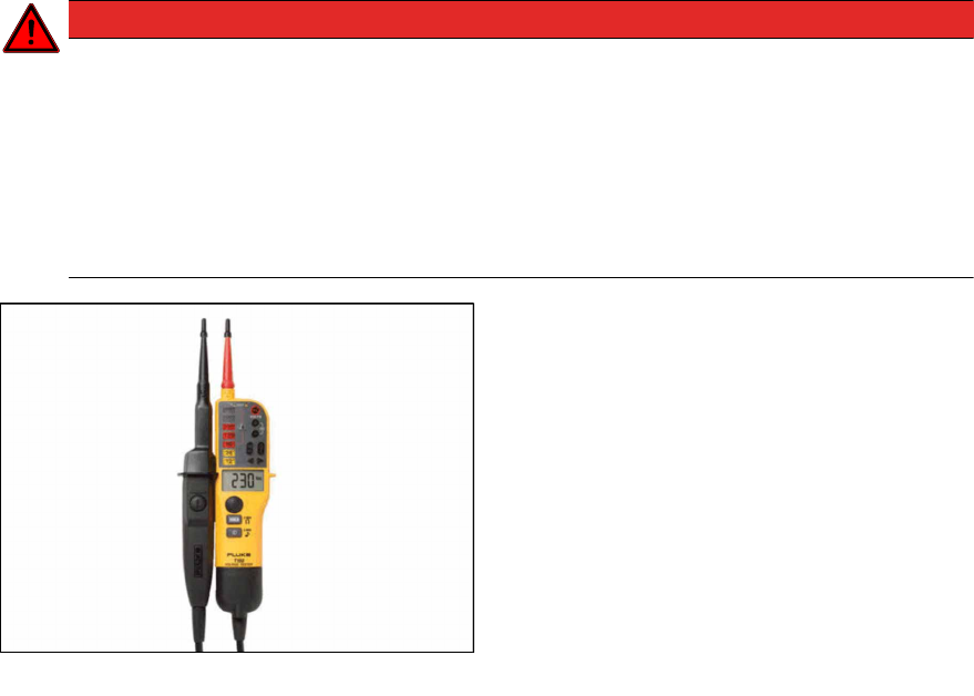
Fig.20: Voltage tester of type "Fluke T-150".
Example:
The figure shows a two-pin voltage tester of
type "Fluke T-150".
This device can be procured world-wide via the
internet or your specialist dealer.
Other, similar devices from other manufacturers
can also be used.
4 Appendix
4.1 Excerpts from the Service Manual
Assembly Instructions / Montageanleitung SIPLACE TX Series
Option 120 V 04/2017
60
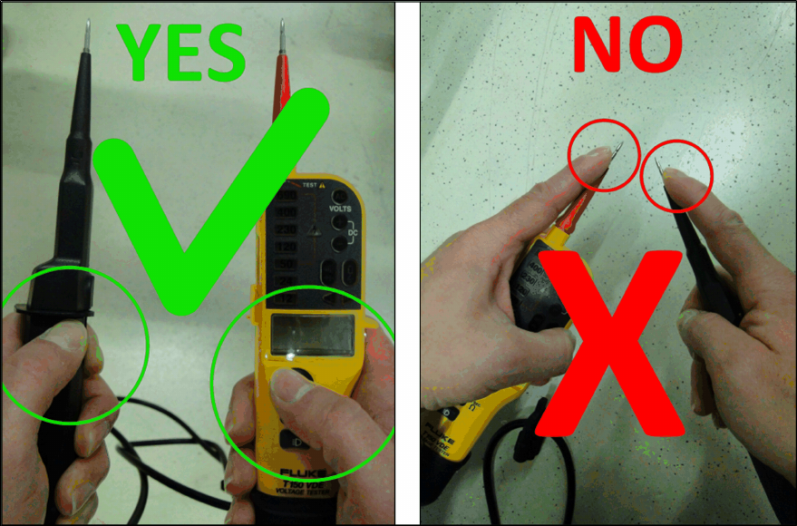
Procedure for Determining Absence of Voltage
Ensure a correct handling of the voltage tester:
●
The measuring device may only be touched by the insulated test handles (up to inside
handles) and the test electrodes (testing tips) may not be touched!
Fig.21: Correct and incorrect handling of the voltage tester
Assembly Instructions / Montageanleitung SIPLACE TX Series
Option 120 V 04/2017
4 Appendix
4.1 Excerpts from the Service Manual
61
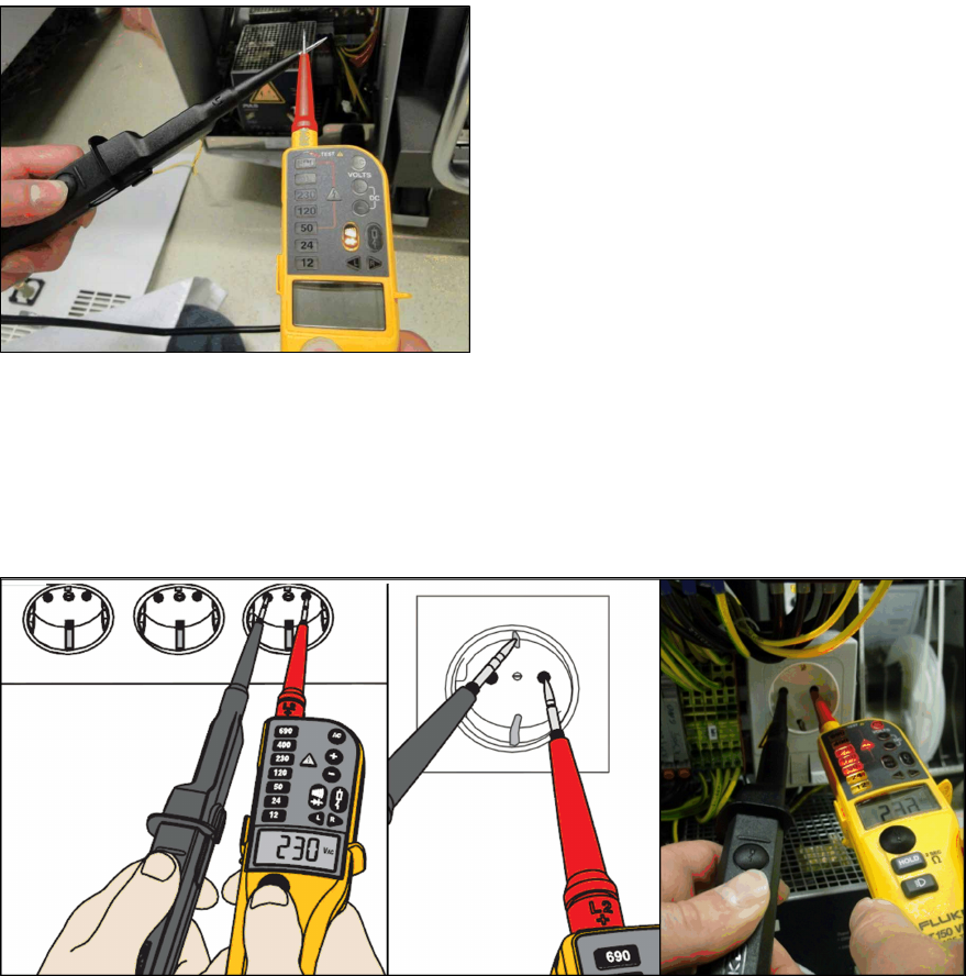
Determining Voltage Tester Functionality
Fig.22: Performing a self-test of the voltage tester
First perform a self-test of the voltage tester.
Touch the two testing tips together.
The voltage tester will be checked for through-
put and the LED throughput display must be vis-
ible and an audio signal must be heard.
After approx. three seconds you can disconnect
the two testing tips again.
Measurement with Known Reference Voltage
To conclude the self-test, check the voltage tester with a known reference voltage.
You can use the service socket on the power supplier (disabled with "110V option") or any other
electrical socket.
Measure the voltage present between the pins and at PE (ground).
Fig.23: Test with reference voltage