00198146-01_AI_120V_TX12_de_en - 第61页
Assembly Instructions / Montageanleitung SIPLACE TX Series Option 120 V 04/2017 4 Appendix 4.1 Excerpts from the Service Manual 61 Determining Voltage Tester Functionality Fig.22: Performing a self-test of the voltage t…
4 Appendix
4.1 Excerpts from the Service Manual
Assembly Instructions / Montageanleitung SIPLACE TX Series
Option 120 V 04/2017
60
Procedure for Determining Absence of Voltage
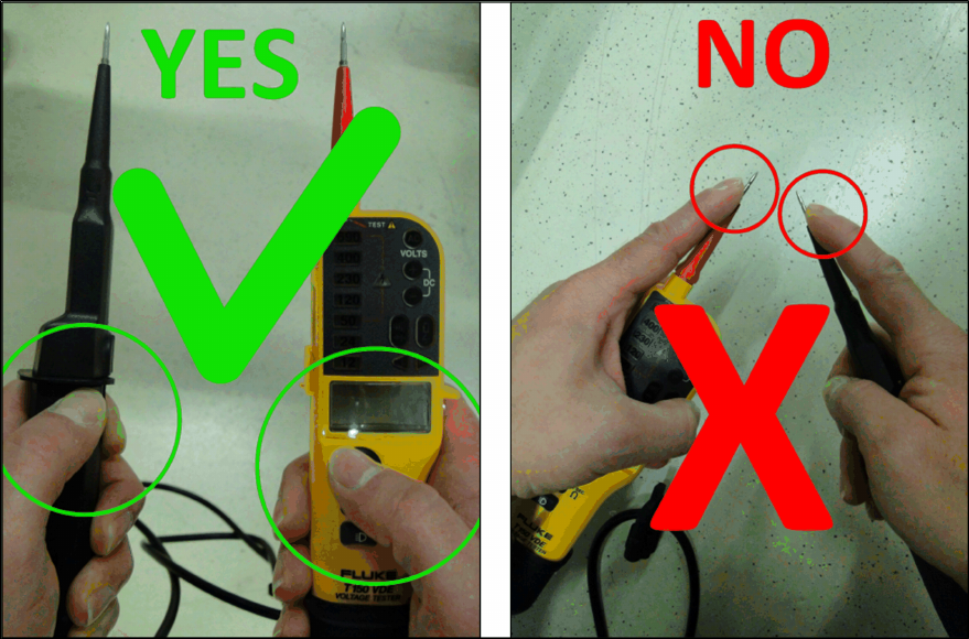
Ensure a correct handling of the voltage tester:
●
The measuring device may only be touched by the insulated test handles (up to inside
handles) and the test electrodes (testing tips) may not be touched!
Fig.21: Correct and incorrect handling of the voltage tester
Assembly Instructions / Montageanleitung SIPLACE TX Series
Option 120 V 04/2017
4 Appendix
4.1 Excerpts from the Service Manual
61
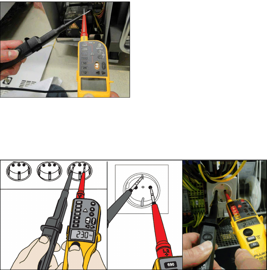
Determining Voltage Tester Functionality
Fig.22: Performing a self-test of the voltage tester
First perform a self-test of the voltage tester.
Touch the two testing tips together.
The voltage tester will be checked for through-
put and the LED throughput display must be vis-
ible and an audio signal must be heard.
After approx. three seconds you can disconnect
the two testing tips again.
Measurement with Known Reference Voltage
To conclude the self-test, check the voltage tester with a known reference voltage.
You can use the service socket on the power supplier (disabled with "110V option") or any other
electrical socket.
Measure the voltage present between the pins and at PE (ground).
Fig.23: Test with reference voltage
4 Appendix
4.1 Excerpts from the Service Manual
Assembly Instructions / Montageanleitung SIPLACE TX Series
Option 120 V 04/2017
62
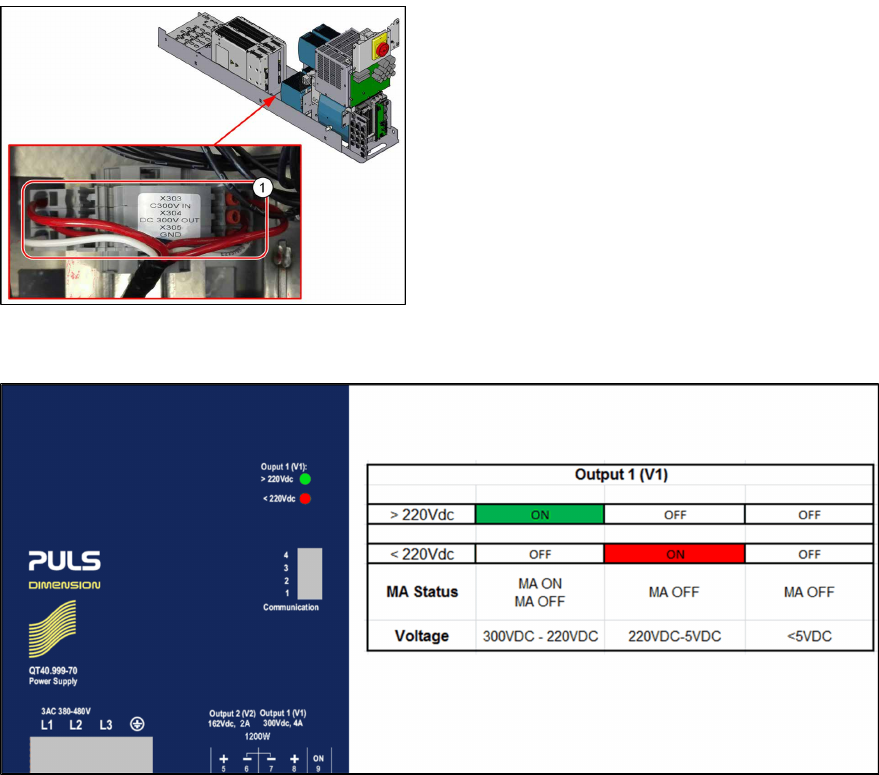
Measuring the Voltage Absence Directly After Switching Machine Off
When the machine has been switched off, the full voltage is still present at the measurement points
X303 (in) and X304 (out).
Measurement is always performed at the reference point X305 (GND)!
► Pull the power supply out towards the front (see Pulling out the Power Supply).
Fig.24: Measuring points
1. Measuring points at power supply
Test 300V IN_X303-X305:
Currently present voltage
Test 300V OUT_X304-X305:
LED display Output 1 at AC/DC converter
Green: Voltage over 220V
The power pack shows an LED display for output
1 > 220 V in green, which means that the voltage
is still over 220 V!
The following figure explains the LED status of the PS1 power pack (300 VDC):
Fig.25: LED status PS1-PS2 300VDC