QP-242E-11.pdf - 第5页
O v e r v i e w 配置図 QP-242E P ARTS LIST ver1 1 O v e r v i e w 配置図 7 8 7 7 . 2 8 2 7 9 8 1 8 0 8 3 7 7 . 1 6 7 . 2 6 8 . 2 7 5 7 1 . 2 7 4 7 3 7 2 7 1 . 1 6 8 . 1 9 2 9 1 6 9 7 0 6 7 . 1 6 3 . 1 6 3 . 2 2 7 2 1 2 2 2 3…

納入後第三者への転売をお考えの際には、必ず事前に弊社へご連絡下さい。
Consult FUJI beforehand if you are considering selling
this equipment to a third party after it has been installed.
パ−ツリストをご利用される前に
1.部品は、図番、コ−ド番号、個数、品名、および規格で発注下さい。
この発注方法以外で発注された場合は発注部品に間違いが生じる恐れがあります。
2.本パ−ツリストは改良のため予告なく変更することがあります。
3.リスト左端の番号が抜けて順番に記載されていない箇所がありますが、これは記載モレや作成途中ではなく
今まで使用していた部品が設計変更により使用されなくなり表から削除されたものです。同時にイラスト内の部品も削除されています。
4.ボルト類,ナット類およびワッシャ類などは種類のみ記載してあります。それぞれの個数は記載せず空欄となっています。
図面原稿 : 2001年 6月
11JE発行 : 2001年 8月
Before Using the Parts List
1. Specify a part number, code number, quantity, part name and rating when ordering parts.
2. This parts manual is subject to change without notice.
3. There are cases where there are no numbers in the left hand column of the parts list. This is not because they were omitted or
the list is incomplete but because the parts to which the numbers applied were eliminated due to a design change.
In such cases the parts have also been removed from the figures.
4. Only the part types are described for nuts, bolts and washers. The quantity column is left blank.
Blueprints created : JUN 2001
11JE released : AUG 2001
5.設計変更した部品(図番の下一桁をカウントアップした部品)は設計変更前の部品と互換です。
しかし、設計変更前の部品は設計変更後の部品と互換であるとは限りません。
例:ABC1231はABC1230と互換であるが、ABC1230がABC1231と互換であるとは限りません。
5. A redesigned part (the last digit of the part number is incremented) is compatible with a part before the redesign.
However,the original part is not always compatible with the revised part,e.i.,ABC1231 is compatible with ABC1230,but
ABC1230 is not always compatible with ABC1231.
TOP
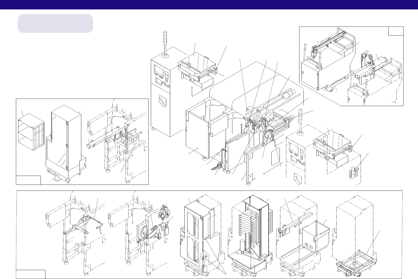
Overview 配置図
QP-242E PARTS LIST ver11
Overview 配置図
78
77.2
82
79
81
80
83
77.1
67.2
68.2
75
71.2
74
73
72
71.1
68.1
92
91
69
70
67.1
63.1
63.2
27
21
22
23
24.1
24.2
25.1
25.2
26.1
26.2
26.3
26.4
26.5
28
20
19
18
7
6
5
4
3
2
1.2
1.1
93
66
76
85
87
86
84
56
57
58
37
36
35
40
39
40
39
38
37
36
35
31
30
29
34
33
32
38
65
64.1.Pneumatic circuit diagram
64.2.Pneumatic circuit diagram
88.MTU-71E Remover pneumaticcircuit diagram
89.MTU-71E Connection related Parts(**-6**)
90.MTU-71E Connection related Parts(**-8**)
94.STU Pneumatic circuit diagram(Option)
41.Conveyor connection related parts
59.Cover 4
60.Cover 5(Sliding door)(Option)
61.Cover 6(Independent)(Option)
62 Fixed device
配置番号は目次番号です。
Refer to contents for
the part name of each number
MFU
42
43
54
55
44
45
46
47
48
49
50
51
52
53
8
9
10
11
12
13
14
15
16
17
MTU-71E
MTU-6E
QP-242E PARTS LIST ver11
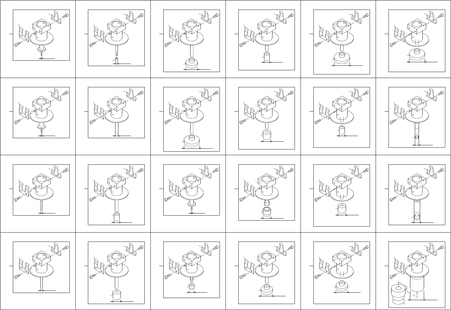
1.1.ノズル一覧(シングルタイプ)(BHPN)
1.1.Nozzles(Single type)(BHPN)
1 - 1
1.1.ノズル一覧(シングルタイプ)(BHPN)
1.1.Nozzles(Single type)(BHPN)
Ref.33-7
タテx173.205
Ref.31-1
Ref.31-1
Ref.31-1
Ref.33-7
S-R30F-037-270
1
2
S-R30F-007-270
21
1
2
S-R30F-013-270
11
1
2
φ3.75
φ0.71
φ1.3
S-R30F-018-270
12
1
2
φ1.81
S-R30F-025-270
13
1
2
φ2.5
15
S-R30F-025G-270
3
1
2
φ2.5
14
4
φ6.5
S-R30F-070-100
5
1
2
φ7.0
29
S-R30F-065G-185
1
2
23
S-R30F-010-270
10
1
2
φ1.0
S-R30F-100G-185
9
1
2
26
φ10
S-R30F-175G-270
40
1
2
φ17.5
36
S-R30F-100-270
6
1
2
18
φ10
S-R30F-150-270
7
1
2
φ15
19
S-R30F-200-270
8
1
2
φ20
20
S-R30F-070-185
5
1
2
φ7.0
24
S-R30F-100-185
6
1
2
25
φ10
S-R30F-150-185
1
2
27
S-R30F-100-100
6
1
2
30
φ10
7
φ15
S-R30F-150-100
1
2
31
7
φ15
S-R30F-070-270
5
1
2
φ7.0
17
S-R30F-050G-270
37
1
2
φ5.0
33
S-R30F-080G-270
38
1
2
φ8.0
34
S-R30F-200-185
1
2
28
8
φ20
8
φ20
S-R30F-200-100
1
2
32
x
208
176
165
175
161
175
161
175
161
183
162
176
167
175
161
13
13
B
A
139
26