DECAN_S1_Administrator′s_Guide(Eng_Ver1.5)_Print.pdf - 第102页
4-20 Next Generation, Multi-Functional Plac er DECAN S1 Administrator’s Guide <Origin> comb o box Select the method of choosing the reference origin. Selectable reference origin is as follows. Machine Logical: As…

4-19
Tools Shortcut Menu
<Head Device> combo box
Select the object becoming the reference of the coordinates for the corresponding
position when moving to the position setup in the <Position> area using the driving
motor selected in the <Axis> combo box. Selectable objects are as follows;
Fid Cam1: Set the coordinate based on the position of the front fiducial camera.
Head1~Head10: Set the position coordinates based on the positions of the #1 ~
#10 heads.
The SM421 Model set the position coordinates based on the positions of the #1 ~
#4 heads.
<Speed Level> group
Select the speed level while operating the selected driving motor.
Selectable speed levels are as follows;
1: Operate the selected motor at the fastest speed.
2: Operate the selected motor at the fast speed.
3: Operate the selected motor at the middle speed.
4: Operate the selected motor at the slow speed.
5: Operate the selected motor at the slowest speed.
<Position> group
Used for inputting the coordinates of the position to move, moving the object as a
reference to the selected device for the position of inputted coordinates, and obtaining
the present coordinates of the object. The values input in the edit box are as follows.
X: Coordinates of X-axis
Y: Coordinates of Y-axis
If the selected object is the motor for adjustment of conveyor width, the input
value is not the Y coordinate but rather the conveyor width.
Z: Coordinates of Z-axis
R: Angle of Theta-axis
<Move> button
Used for moving the object to the position of input coordinates with reference to
the selected device.
<Get> button
Obtain the present position (coordinates or angle) of the selected object and
indicate the result in the status indication area.
<Find Surface Touch Z Height> button
It is used to check the Z axis height at the point in the work area according to the
selected device. It is enabled when selecting ‘Z’ in the <Axis> combo box.
4-20
Next Generation, Multi-Functional Placer DECAN S1 Administrator’s Guide
<Origin> combo box
Select the method of choosing the reference origin. Selectable reference origin is as
follows.
Machine Logical: Assign the origin of equipment as a reference origin.
FeederBase Front (1): Assign the origin of the front feeder row as a reference origin.
FeederBase Rear (2): Assign the origin of the rear feeder row as a reference origin.
Status Indication Area
Indicates the information generated during manual operation.
<Park Front> button
Move the front gantry near to the front ANC, and the rear gantry near to the Y2 +
Limit position.
<Park Rear> button
Move the front gantry near to the Y1 + Limit position, and the rear gantry near to the
rear ANC.
<Advanced Surface Measure> button
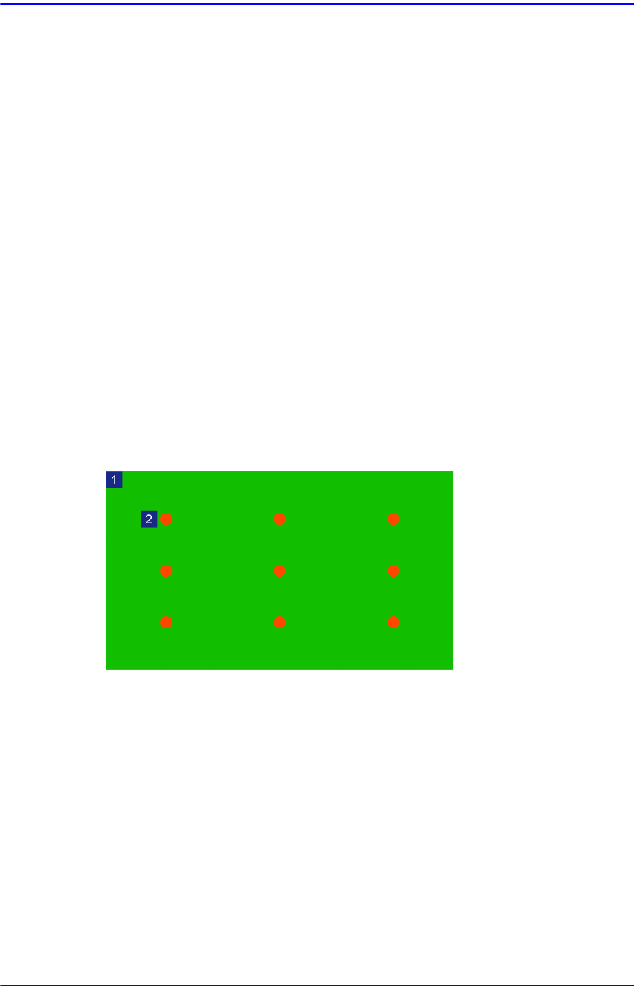
Perform setup of the value with which the flatness of a board is checked by teaching
nine points on the board.
1: Board
2: Teaching Point
4-21
Tools Shortcut Menu
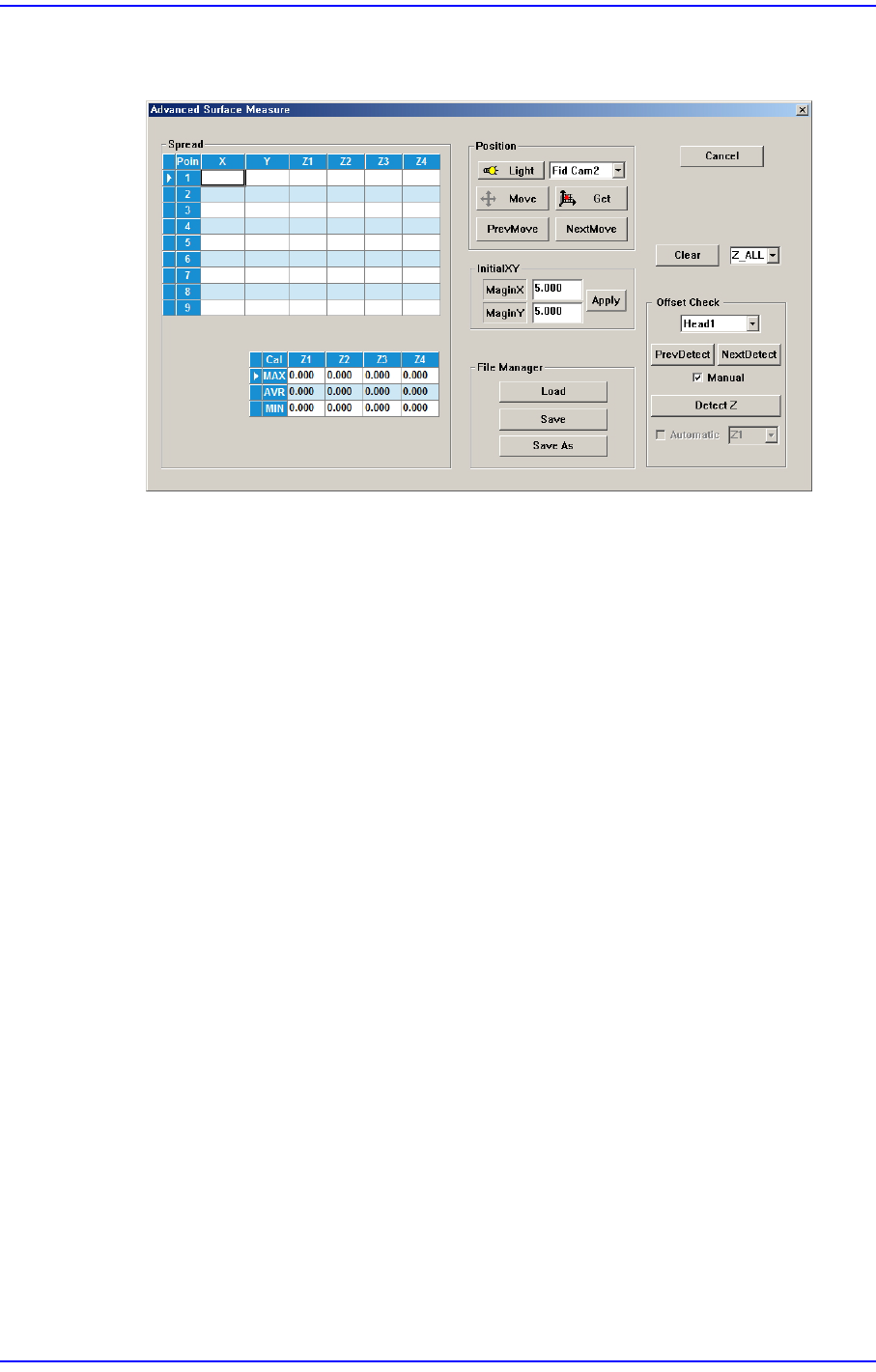
Clicking the <Advanced Surface Measure> button will display the following dialog
box.
<Spread> group
The X and Y values are registered automatically by calculating the margin
inputted in the <InitialXY> group.
<Point> column
Refers to the position at which the board flatness is to be measured.
<X> column
Refers to the X position value of the flatness measuring position.
<Y> column
Refers to the Y position value of the flatness measuring position.
<Z1~4> column
Refers to the Z height value measured at the X and Y positions.
<MAX> row
Shows the maximum value among the Z values obtained by measuring them
at the nine points on the board.
<MAX> row
Shows the average Z value obtained by measuring the values at nine points on
the board.
<MIN> row
Shows the minimum value among the Z values obtained by measuring them at
the nine points on the board.