DECAN_S1_Administrator′s_Guide(Eng_Ver1.5)_Print.pdf - 第166页
7-2 Next Generation, Multi-Functional Plac er DECAN S1 Administrator’s Guide When the ‘Part’ submenu is selected, the initial screen is as follows. Figure7.2 “Pa rts” dialog box <1. PCB Part List> group Display a…
7-1
Part Registration
Chapter7. Part Registration
The <Part> command is used to register components necessary for PCB operation and edit
data.
Part data is composed of “Align Data” and “Common Data”.
Align Data
Consists of information related to part recognition
Common Data
Consists of parameters related to part feeding device, nozzle for part pickup and
placement, pneumatic condition and driving speed
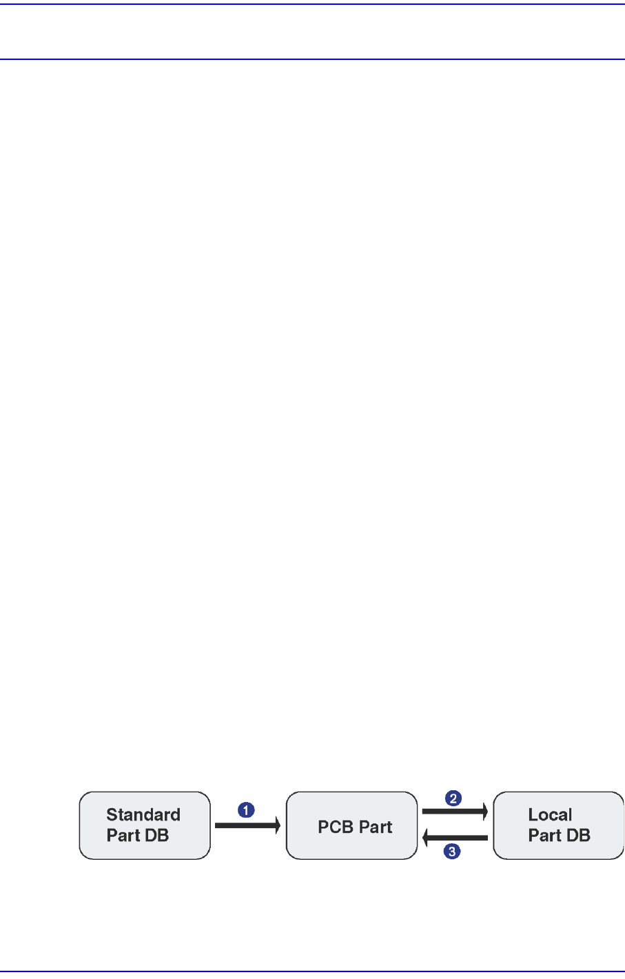
The component data managed by MMI include PCB Part, Local Part, and Standard Part
DB.
PCB Part: Parts registered in the PCB file
Local Part DB [UPD.mdb]: Parts registered after installing MMI in the equipment
Standard Part DB [STDUPD.mdb]: Simultaneous installation with MMI is DB
managing the data for standard parts (Read only)
Each PCB controls component data on all components operated on the corresponding PCB
and saves the component data in the Local Part DB of the machine.
To create component data for a new PCB, component data stored in the Local Part DB can
be copied. To create component data for a new component whose data is not stored in the
Local Part DB, data for a similar component stored in the Local Part DB can be copied and
edited or standard component data can be copied from the Standard Part DB and edited.
The Standard Part DB is a DB of generally used components developed and supplied by
this machine manufacturer. The relationship between component data is shown in the
following.
Figure7.1 Relationship between component DBs
Applied to all PCBs Controlled by each PCB Controlled by
each machine
1: Create new part
2: Save
3: Copy
7-2
Next Generation, Multi-Functional Placer DECAN S1 Administrator’s Guide
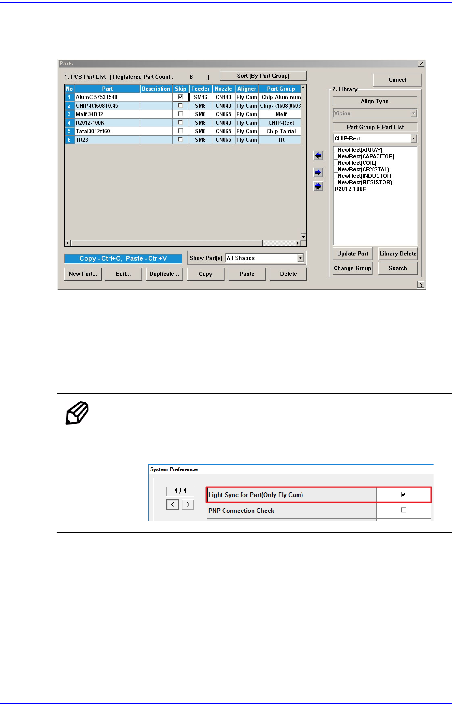
When the ‘Part’ submenu is selected, the initial screen is as follows.
Figure7.2 “Parts” dialog box
<1. PCB Part List> group
Display a list of currently registered components.
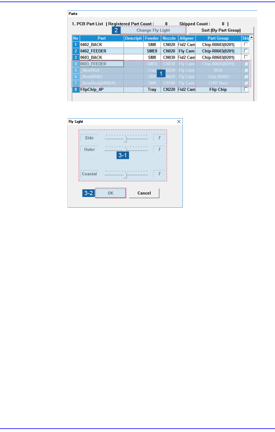
<Change Fly Light> button
It is used when it is necessary to perform a batch change of the lighting value of
parts that use the fly camera.
Memo To activate the <Change Fly Light> button, the option “Light Sync
for Part (Only Fly Cam)” must be set in the “Preferences” submenu of
the “System Setup” menu.
A batch change of the lighting value can be performed as follows.
1. Select the parts that use the fly camera from the parts list displayed in the <1.
PCB Part List> group.
7-3
Part Registration
2. Click the <Change Fly Light> button.
3. After changing the lighting value, click the <OK> button.
<Sort (By Part Group / Name)> column
Sorts the parts list displayed in the <1. PCB Part List> group by part group/name.
(In ascending order)
<Part> column
Displays the component name.
<Feeder> column
Displays the type of the feeder supplying components.
<Nozzle> column
Displays the nozzle that pick up components. The nozzle types are as follows;
<Aligner> column
Indicates the camera used to recognize a part.
<Part Group> column
Displays the component Part Group.
<Skip> column
When it is checked, this part is skipped during placing