DECAN_S1_Administrator′s_Guide(Eng_Ver1.5)_Print.pdf - 第167页
7-3 Part Registration 2. Click the <Change F ly Light> button. 3. After changing the lighti ng value, click the <OK> button. <Sort (By Part Group / Name)> column Sorts the parts list displayed in the …
7-2
Next Generation, Multi-Functional Placer DECAN S1 Administrator’s Guide
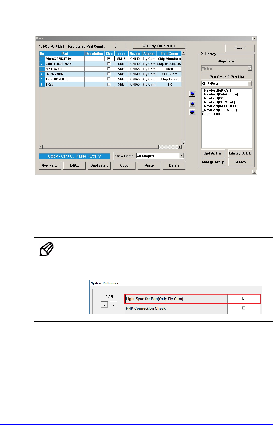
When the ‘Part’ submenu is selected, the initial screen is as follows.
Figure7.2 “Parts” dialog box
<1. PCB Part List> group
Display a list of currently registered components.
<Change Fly Light> button
It is used when it is necessary to perform a batch change of the lighting value of
parts that use the fly camera.
Memo To activate the <Change Fly Light> button, the option “Light Sync
for Part (Only Fly Cam)” must be set in the “Preferences” submenu of
the “System Setup” menu.
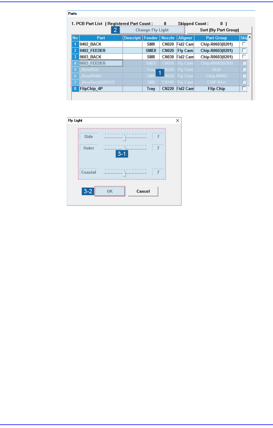
A batch change of the lighting value can be performed as follows.
1. Select the parts that use the fly camera from the parts list displayed in the <1.
PCB Part List> group.
7-3
Part Registration
2. Click the <Change Fly Light> button.
3. After changing the lighting value, click the <OK> button.
<Sort (By Part Group / Name)> column
Sorts the parts list displayed in the <1. PCB Part List> group by part group/name.
(In ascending order)
<Part> column
Displays the component name.
<Feeder> column
Displays the type of the feeder supplying components.
<Nozzle> column
Displays the nozzle that pick up components. The nozzle types are as follows;
<Aligner> column
Indicates the camera used to recognize a part.
<Part Group> column
Displays the component Part Group.
<Skip> column
When it is checked, this part is skipped during placing
7-4
Next Generation, Multi-Functional Placer DECAN S1 Administrator’s Guide
<2. Library> group
Display the component list of the Local Part DB managed by the machine.
<Align Type> combo box
Select the align type of the component to be displayed. The Vision Align is used as
default.
Vision: Alignment by the Vision Camera. Recognize the part.
<Part Group & Part List> group
Select the group of component to be displayed. Available component groups are as
follows;
(CHIP-Circle, CHIP-Rect, Chip-Tantal, Chip-Aluminum, Melf:, TR: TR2:,
Trimmer:, Hemt:, SOP:, SOJ:, SOP2:, SOJ2:, QFP:, PLCC:, PLCC[body]:
Connector, User IC:, BGA, Multi-BGA, Flip Chip )
<Part List> list box
Displays the component data list of the data selected in <Align Type> and
<Part Group>. The parts corresponding to the conditions selected from the
Standard Part DB and Local Part DB are indicated.
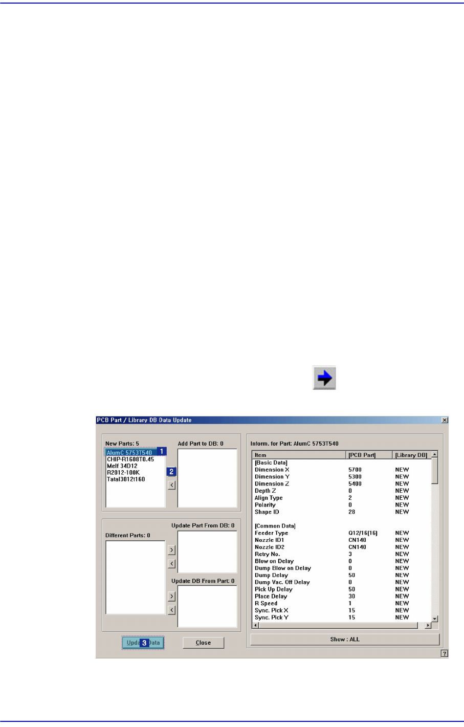
<Update Part> button
Used for adding to the local DB after registering a new part. Select the newly
registered part in the <1. PCB Part List> first, and copy it to the <Part List> box of
the corresponding part group by clicking on the button. Select the part
copied to the <Part List> list box and click on this button.
<New Parts:> list box
Indicates parts which are not registered in the local part DB among the parts