DECAN_S1_Administrator′s_Guide(Eng_Ver1.5)_Print.pdf - 第190页
7-26 Next Generation, Multi-Functional Plac er DECAN S1 Administrator’s Guide Figure7.8 “Camera No. = Fix Camera“ dialog box <Side> slide bar Set a value for the side light. (0 –15) <Outer> slide bar Set …
7-25
Part Registration
7.1.1. Common Align Data
Provides details concerning the align data commonly applied to all parts.
<Camera No.> combo box
Fly Cam: Selects the fly camera of the head.
Memo The fly camera for recognizing each head is as follows:
Fly Cam1: Head #1~Head #2 of the front gantry
Fly Cam2: Head #3~Head #4 of the front gantry
Fly Cam3: Head #5~Head #6 of the front gantry
Fly Cam4: Head #7~Head #8 of the front gantry
Fly Cam5: Head #9~Head #10 of the front gantry
Fix Cam1: Select the fix camera.
button
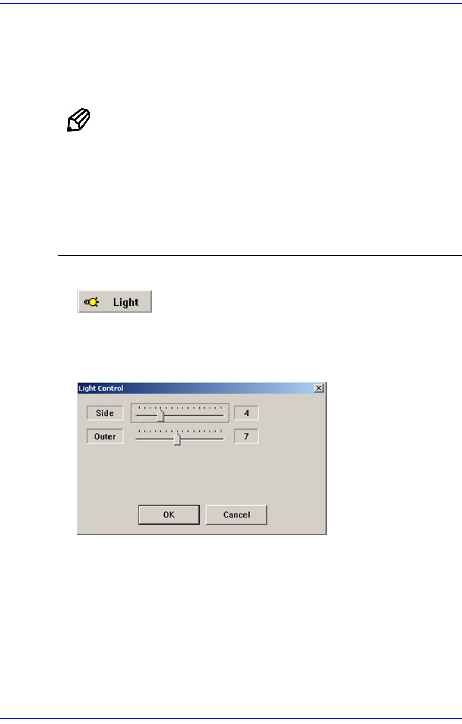
Sets the lighting for the camera to recognize the component. When this button is
clicked on, the following dialog box is displayed.
Figure7.7 “Camera No. =Fly Camera“ dialog box
7-26
Next Generation, Multi-Functional Placer DECAN S1 Administrator’s Guide
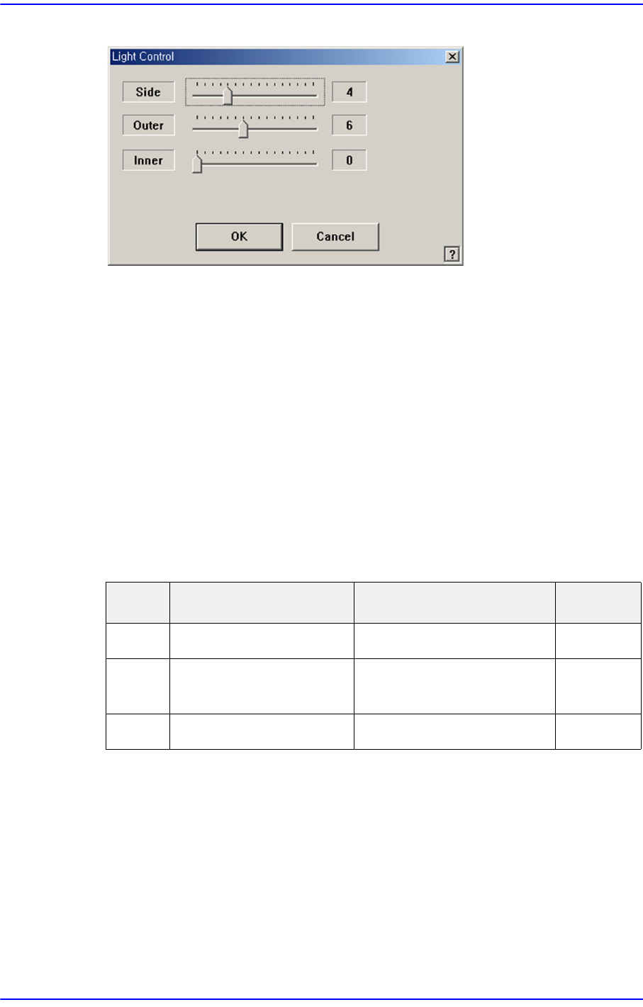
Figure7.8 “Camera No. =Fix Camera“ dialog box
<Side> slide bar
Set a value for the side light. (0 –15)
<Outer> slide bar
Set a value for the outer light. (0 - 15)
<Inner> slide bar
Set a value for the outer light. (0 - 15)
<OK> button
Saves the set light value and closes the dialog box.
<Cancel> button
Closes the dialog box without saving the set light value.
Table7.1 Use of the Fix Camera Lighting
<Size> group
<Align Z> edit box
Set the height for recognition. Based on the component surface, if the top is to be
recognized, set - value, and if the bottom is to be recognized, set +value.
<Threshold> edit box
The image viewed through the SM Vision window is composed of each pixel.
Each pixel has a unique value between 0 and 255 according to the seen degree of
brightness. Here, ‘Threshold Value’ indicates the border value deciding whether
Light Use Applicable Part Remarks
Side Lights the edge of a part Chip, QFP, BGA, SOP etc
Outer Lights round edge of a
part or part surface
Chip, QFP, BGA, SOP etc
Inner Lights a part surface Chip, QFP, BGA, SOP etc

7-27
Part Registration
each pixel should be recognized in white or black.
<Auto> check box
Check this box to set the <Threshold> value automatically.
<Tolerance H[+]> edit box
In general, a part has a manufacturing tolerance. When the size of the recognized
part is larger than that in the registered part data, if its tolerance is not considered,
its inspection result will be no good.
Therefore, when recognizing a part, input the extent of the allowable difference
between the actual size and registered size as a percentage.
That is, when the value obtained by recognizing an actual part with the vision
system is greater than the input value, if the actual data value is allowed up to 1.3
times of the input data, the upper allowable error is 30%.
For the following chip parts, set the parameters referring to the following. For
other chip parts, it is recommended that the default setup be used.
Chip-Circle
An allowable error is applied not to the length but to the area.
If an allowable error is applied to 10% of the diameter, the square of the
diameter must be applied. Therefore, 21% of the diameter is actually applied.
(Tolerance (H, L) = 1.1×1.1=1.21 )
Chip-C 0402 / Chip-R 0402 / Chip-C 0603 / Chip-R 0603/ Chip-R 1005
Set it to a value greater than the one to be set by more than 10%. For example,
when setting 20%, actually apply 30%.
<Tolerance L[-]> edit box
If the size of the recognized part is smaller than the registered part data, input the
allowable error as a percentage.
That is, when the actually recognized value is smaller than the input value, if the
actual data value is allowed up to 0.7 times that of the input data, the lower
allowable error is 30%.
For the following chip parts, set the parameters referring to the following. For
other chip parts, it is recommended that the default setup be used.
Chip-Circle
An allowable error is applied not to the length but to the area.
If an allowable error is applied to 10% of the diameter, the square of the
diameter must be applied. Therefore, 21% of the diameter is actually applied.
(Tolerance (H, L) = 1.1×1.1=1.21)
Chip-C 0402 / Chip-R 0402 /Chip-R 1005
Set it to a value greater than the one to be set by more than 10%. For example,