DECAN_S1_Administrator′s_Guide(Eng_Ver1.5)_Print.pdf - 第204页
7-40 Next Generation, Multi-Functional Plac er DECAN S1 Administrator’s Guide Light Level Displays the current light level. Image Capture Range Displays the range and interval of the light level change to be used for…
7-39
Part Registration
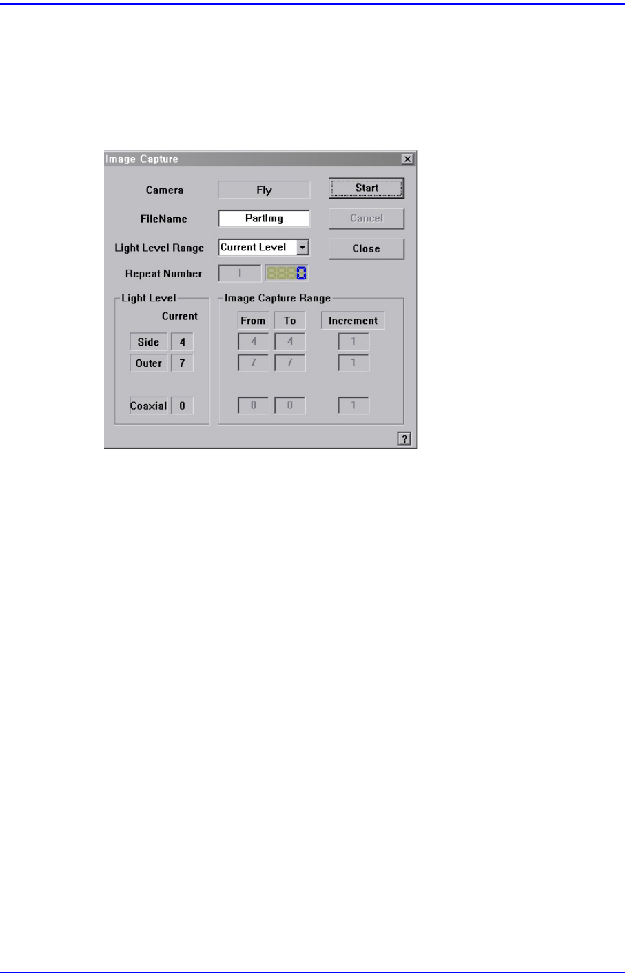
<Image Capture> button
Helps to specify the optimum lighting value. The lighting is gradually changed
automatically and the images are saved. The user can check the best image and
identify the optimum lighting value.
Figure7.11 “Image Capture” dialog box
<Camera> caption box
Displays the camera to be used for image capture.
<Filename> edit box
Enters the filename to be used for image saving.
<Light Level Range> combo box
Enters the filename to be used for image saving.
Rough
Saves the image by increasing the level of each light by 5.
Fine
Saves the image by increasing the level of each light by 1 within the range of
the light level before and after the currently set light level.
All Range
Saves the image for all light levels.
User Define
The user sets the range and interval of the light level change.
Repeat Number
Indicates the number of times an image has been saved.

7-40
Next Generation, Multi-Functional Placer DECAN S1 Administrator’s Guide
Light Level
Displays the current light level.
Image Capture Range
Displays the range and interval of the light level change to be used for saving the
image. If the light level range is set as User Define, the user can directly enter and
correct the range.
From
Displays the starting level of the light level change.
To
Displays the finishing level of the light level change.
Increment
Sets the interval of the light level change.
<Start> button
Starts image capture.
<Cancel> button
Stops image capture.
<Close> button
Closes the dialog box.
7-41
Part Registration
7.1.2. CHIP component data setting
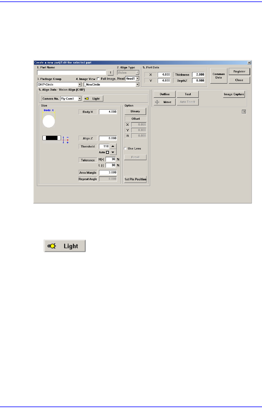
7.1.2.1. CHIP-Circle component data setting
Set the align data for circle CHIP components.
Figure7.12 “Package Group =CHIP-Circle” dialog box
<Camera No.> combo box
Select the camera to recognize the component. Please refer to “7.1.1 Common Align
Data” for more information.
button
Select the light for the camera to recognize the component. Please refer to“7.1.1
Common Align Data” for more information.
<Size> group
Set the align size.
<Body X> edit box
Enter the diameter of the component.
For other setups, please refer to “7.1.1 Common Align Data”.
<Option> group
Set the Option data among Align data related to part recognition.
<Use LED flip check> check box
This is selected to use the function that checks the turnover of the LED. For more
details, refer the “<Detail> Button” of “7.1.2.2CHIP-Rect component data
setting”.