DECAN_S1_Administrator′s_Guide(Eng_Ver1.5)_Print.pdf - 第213页
7-49 Part Registration (Chip-R3216, Chip -R2012, Chip-R1608, C hip-R1005, Chip-R0603, Chip-R0402 etc.) <1st Pin Position> button Used to check the placement a ngle easil y when verifying the placement point offli…
7-48
Next Generation, Multi-Functional Placer DECAN S1 Administrator’s Guide
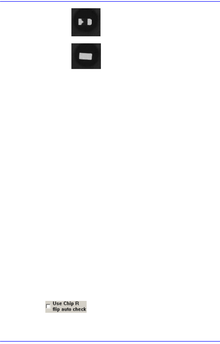
- : OK –Considered to be picked up normally.
- : NG –Considered to be picked up upside down.
<Load default data> button
Shows examples for inputting an LED mark, and indicates the default
value saved in the system regardless of the part actually picked up.
This function is a guide for inputting certain types of value. Since this data
has nothing to do with the part to be actually placed, use the data for
reference only.
In addition, when it is desired to return all values inputted back to the
default value, this function can be used.
It is possible to judge whether inputted values for ‘Area 1’ and ‘Area 2’ are
appropriate by clicking the <Outline> button.
Whether to recognize the polarity must be checked by clicking the <Test>
button. If the recognition result is ‘OK’, when the <Test> button is clicked
again, with the part being turned 180° manually using the jog box, check
whether the recognition result is ‘NG’.
If the setup has been performed properly, click the <Close> button to save the
set value.
<Rough Check> check box
When recognizing a part, if a recognition error occurs because the shape of the
part to be recognized does not match with the vision algorithm data, select this
check box.
If this check box is selected, even if a certain shape of the part to be recognized is
more or less incorrect when compared with the vision algorithm data, the part is
recognized correctly in case it is identical when checking the layout of the entire
parts.
As a part whose leads are slightly bent, it uses a crystal or aluminum capacitor.
This is applied only to Chip-rect, Chip-aluminum, etc.
<Use Chip R flip auto check> check box
This is used only in the Part Edit Screen for Chip R part. It is selected to use the
function that checks the turnover of the Chip R part.

7-49
Part Registration
(Chip-R3216, Chip-R2012, Chip-R1608, Chip-R1005, Chip-R0603, Chip-R0402
etc.)
<1st Pin Position> button
Used to check the placement angle easily when verifying the placement point
offline by registering the No. 1 pin position when registering a part.
Please refer to“7.1.1 Common Align Data” for more information.
<Move> button
Tests component recognition by using the set align data. Please refer to“7.1.1
Common Align Data” for more information.
<Test> button
Tests component recognition by using the set align data. Please refer to“7.1.1
Common Align Data” for more information.
<Image Capture> button
Helps to specify the optimum lighting value. The lighting is gradually changed
automatically and the images are saved. The user can check the best image and
identify the optimum lighting value. Please refer to“7.1.1 Common Align Data” for
more information.
<Auto Teach> button
Automatically finds out the component align data. For more details, refer the “<Use
LED flip check>Check Box”of“7.1.1 Common Align Data” for more information.
7-50
Next Generation, Multi-Functional Placer DECAN S1 Administrator’s Guide
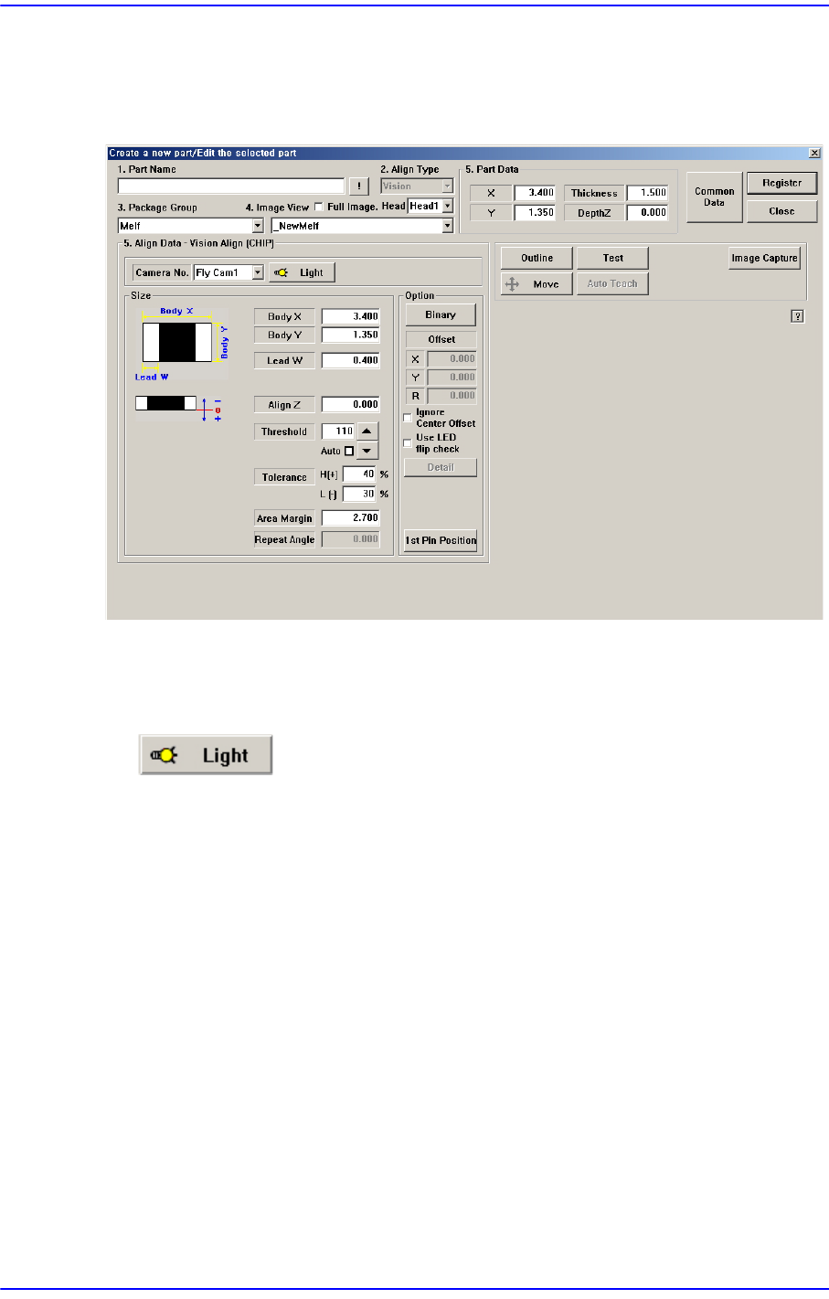
7.1.2.3. Melf component data setting
Set the align data for Melf components.
Figure7.15 “Package Group =Melf” dialog box
<Camera No.> combo box
Select the camera to recognize the component. Please refer to“7.1.1 Common Align
Data” for more information.
button
Select the light for the camera to recognize the component. Please refer to “7.1.1
Common Align Data” for more information.
<Size> group
Set the align size.
<Body X> edit box
Set the component size in X direction.
<Body Y> edit box
Set the component size in Y direction.
<Lead W> edit box
Set the length of lead in X direction.
For other setups, please refer to ““7.1.1 Common Align Data”.
<Option> group
Set the Align Option data.