DECAN_S1_Administrator′s_Guide(Eng_Ver1.5)_Print.pdf - 第250页
7-86 Next Generation, Multi-Functional Plac er DECAN S1 Administrator’s Guide information. <Move> button Used for parts recognition test by manu ally picking up parts. Please refer to “7.1.1 common Align Data” fo…
7-85
Part Registration
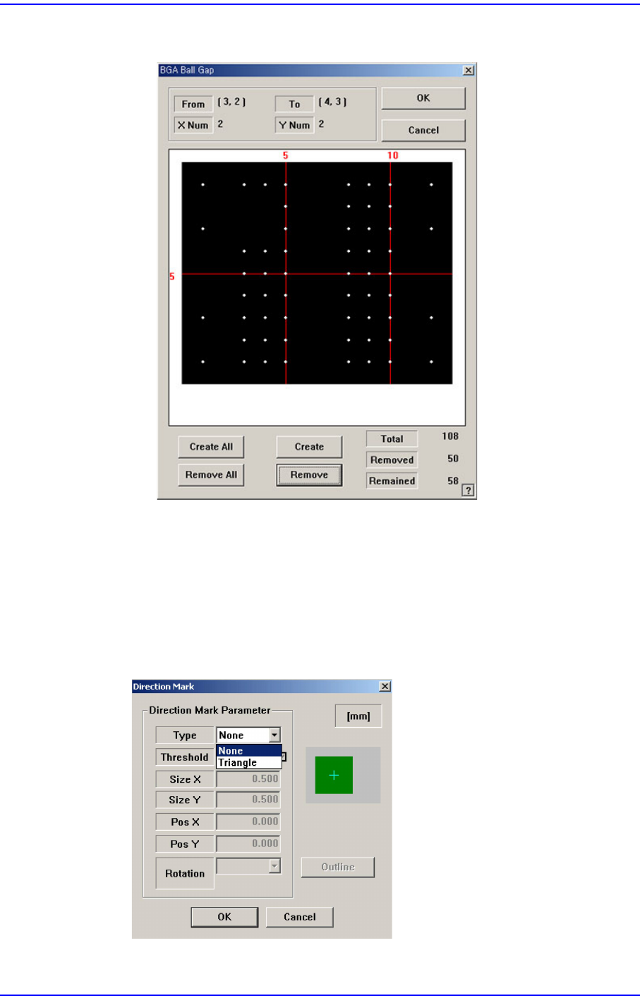
Figure7.30 “Ball Gap of BGA components-when balls in the selected area are
removed” dialog box.
<OK> button
Saves the set ball gap status and closes the dialog box.
<Cancel> button
Closes the dialog box without saving the set ball gap status.
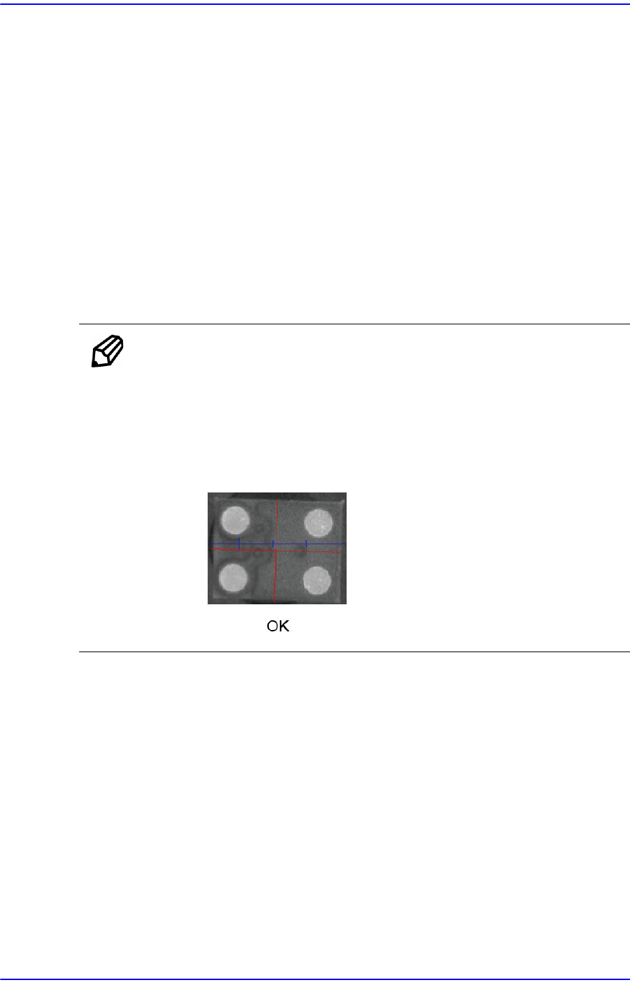
<Direction Mark> button
Set the direction of the BGA.
For details of other than this, refer to “7.1.1 common Align Data” for more
7-86
Next Generation, Multi-Functional Placer DECAN S1 Administrator’s Guide
information.
<Move> button
Used for parts recognition test by manually picking up parts. Please refer to“7.1.1
common Align Data” for more information.
<Test> button
Performs the component recognition test by using the set align data. Please refer
to“7.1.1 common Align Data” for more information.
<Image Capture> button
Helps to specify the optimum lighting value. The lighting is gradually changed
automatically and the images are saved. The user can check the best image and
identify the optimum lighting value. Please refer to“7.1.1 common Align Data” for
more information.
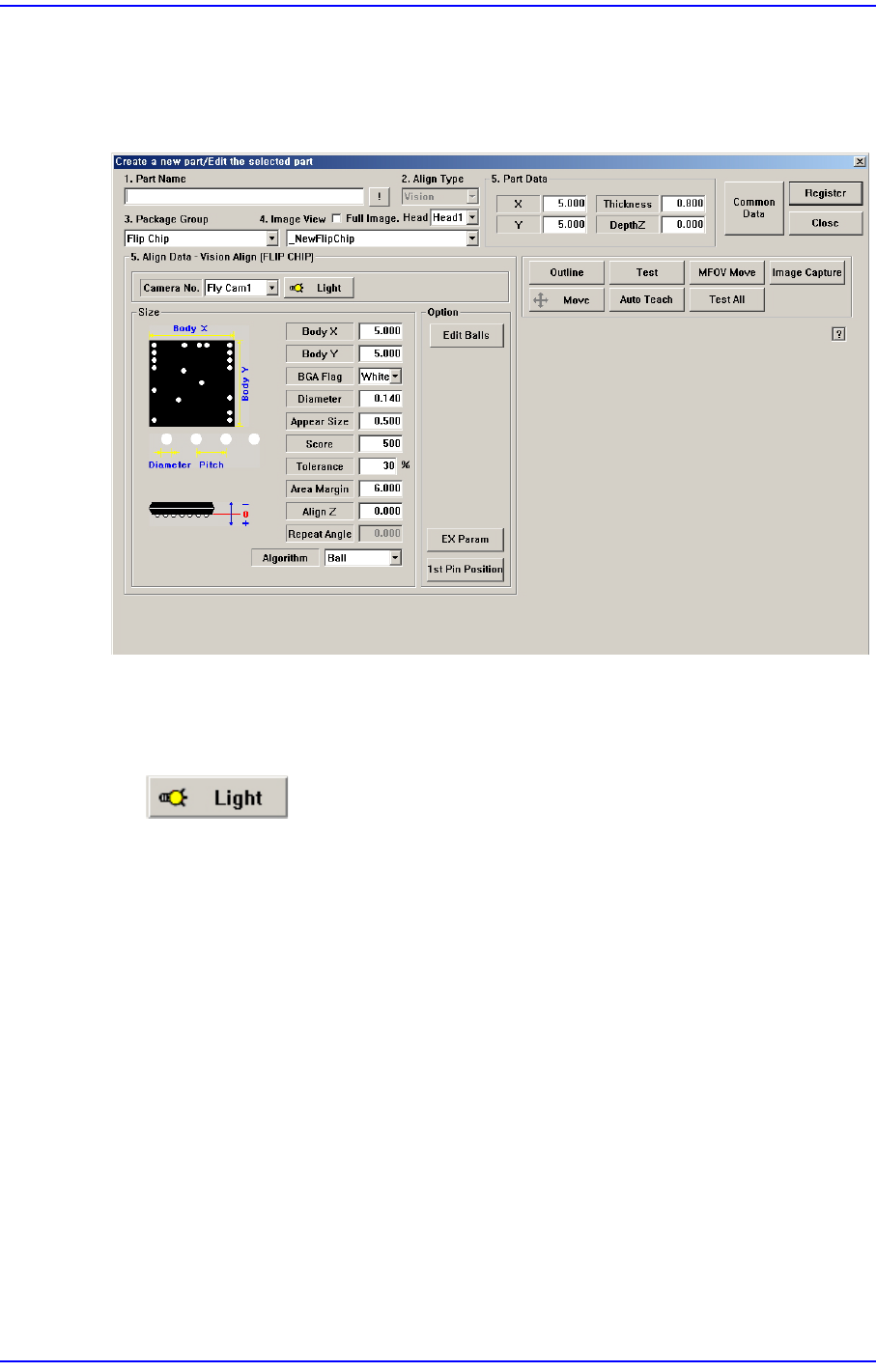
Memo In the case of parts that have less than 5 balls widthwise and
lengthwise respectively as shown in the following image and whose
ball shape is not clearly contrasted with the body, register them as
BGA and have them recognized by reducing their ‘Score’ value.
Otherwise, the score of the recognized image becomes insufficient
and, therefore, a vision recognition error occurs.
7-87
Part Registration
7.1.8. FLIP CHIP component data setting
Set the align data for Flip Chip components.
Figure7.31 “Package Group =Flip Chip” dialog box
<Camera No.> combo box
Select the camera to recognize the component. Please refer to“7.1.1 common Align
Data” for more information.
button
Select the camera to recognize the component. Please refer to“7.1.1 common Align
Data” for more information.
<Size> group
Set the align size. Please refer to “7.1.7 BGA component data setting“ of <Size>
group for more information.
<Option> group
Set the align option data.
<Edit Balls> button
Edits the position of each ball.