DECAN_S1_Administrator′s_Guide(Eng_Ver1.5)_Print.pdf - 第272页
8-14 Next Generation, Multi-Functional Plac er DECAN S1 Administrator’s Guide <Panorama V iew> button In the case of a large part for which pocket teaching is impossible, its entire shape is not displayed in th e…
8-13
Feeder Setup
head and click this button.
<Installed Feeder Only> check box
Shows only the list of the feeders installed in the grid cell group for feeders.
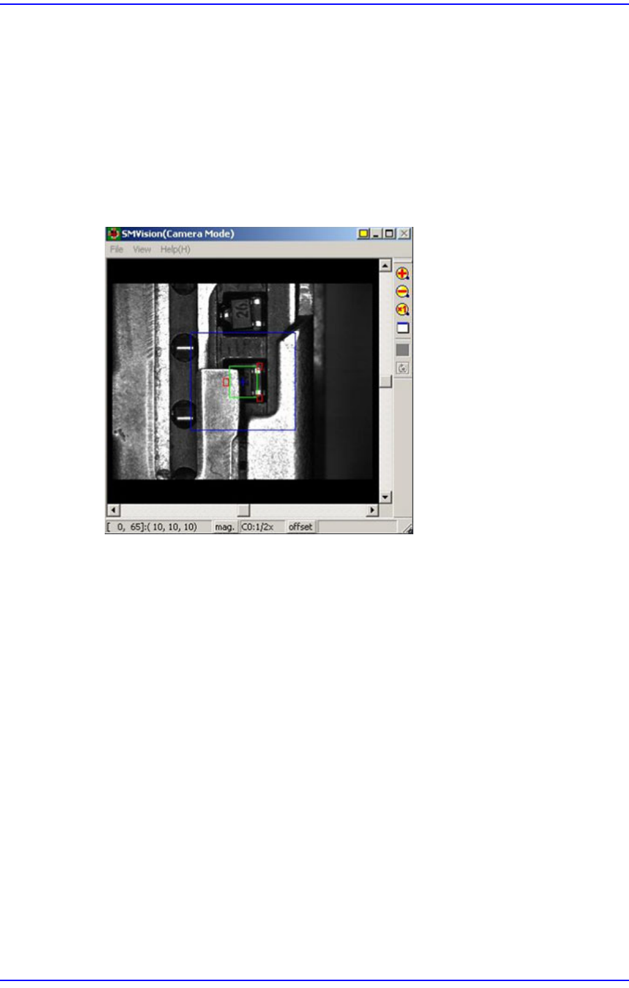
<Part Outline> check box
If this check box is selected, when the fiducial camera is moved to the position of the
corresponding feeder to check the pickup position, the outline image that considers the
angle at which the corresponding part is picked up is displayed on the SMVision
window.
<Offset → Part> button
Selected when applying the pickup offset to the same tape feeder collectively after
changing the pickup coordinate of the installed tape feeder.
<Part → Offset> button
Clicking this button will automatically reflect the pickup offset of the corresponding
part on the pickup coordinate when there are parts with pickup offset among the parts
supplied by the currently installed tape feeders.
8-14
Next Generation, Multi-Functional Placer DECAN S1 Administrator’s Guide
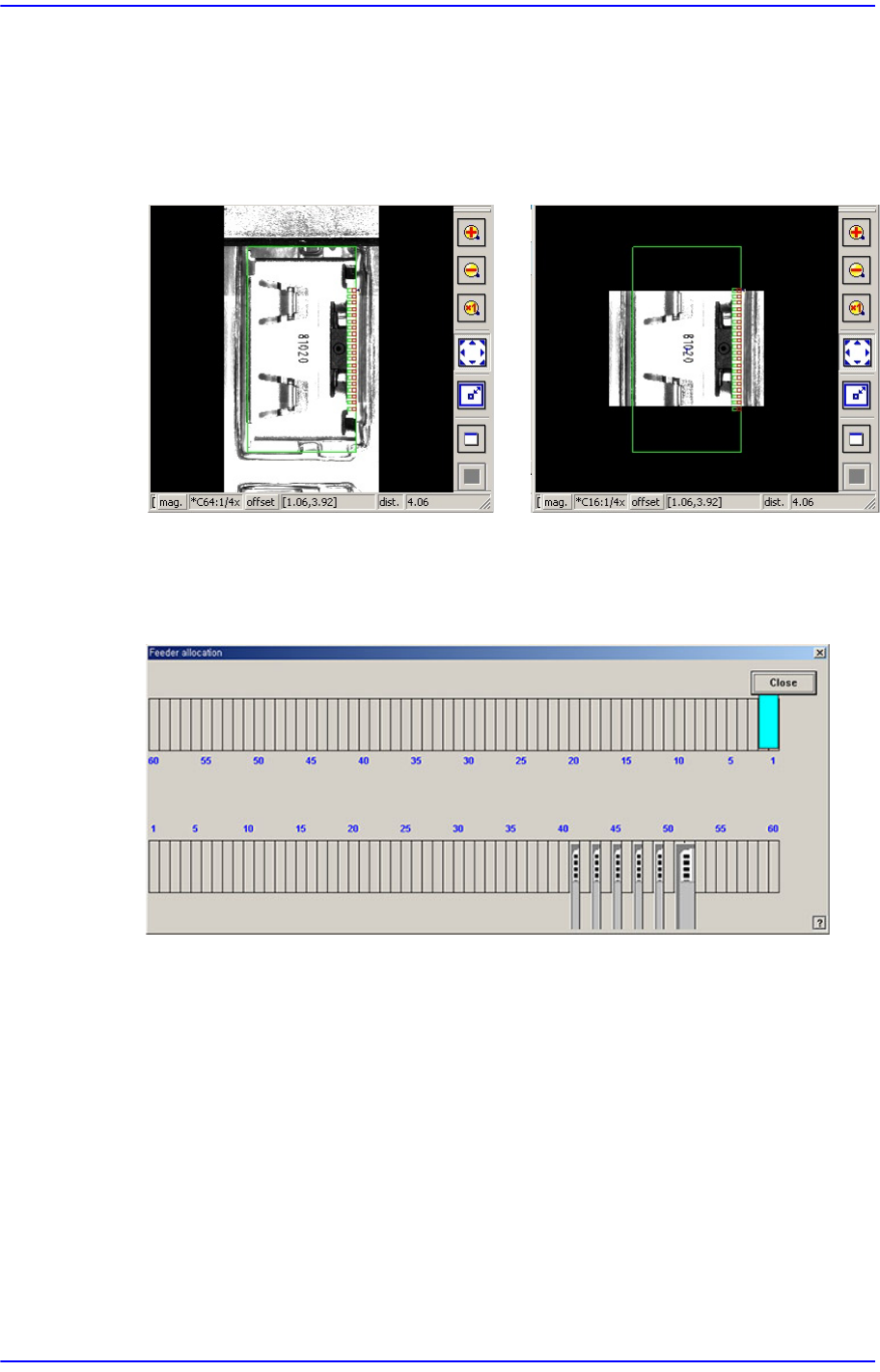
<Panorama View> button
In the case of a large part for which pocket teaching is impossible, its entire shape is
not displayed in the vision window. In this case, it is possible to display the part shape
in on one vision window by performing split recognition of the part shape and
composing the split images into one using this function.
<Display> button
Displays the shape of the feeder that is installed on the feeder base graphically.
<Cancel> button
Close the dialog box.
Panorama General
8-15
Feeder Setup
8.1.2. Stick Unit
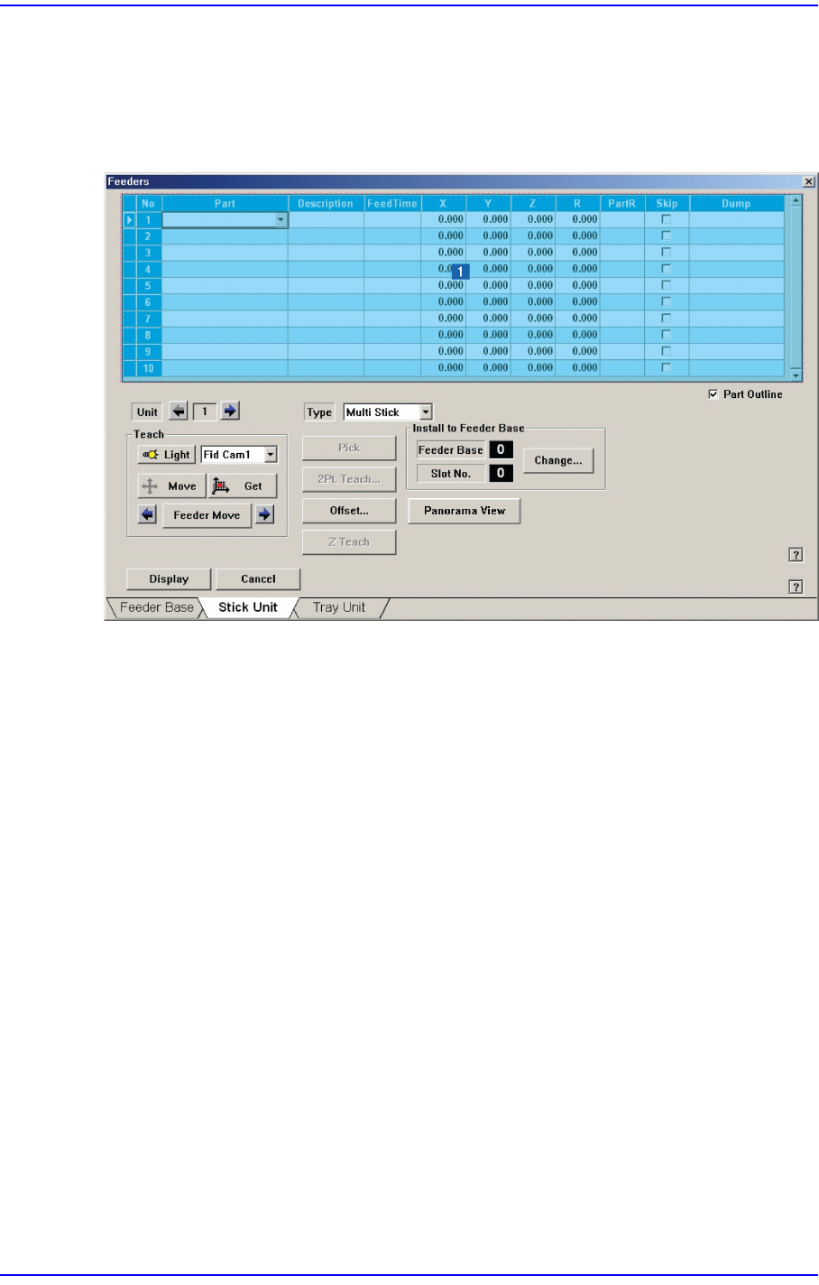
Install stick feeder and set data on the stick feeder. When “Stick Unit” is selected, the
initial screen looks as follows.
Figure8.7 “Stick Unit” dialog box
1: Grid group
<Grid> group
Create and edit data according to the stick unit type selected in the <Type> combo
box.
<No> column
A serial number of the stick unit slots. The number of slots of the stick feeder is as
follows. Serial number is created depending upon the number of slots.
Multi Stick - Max. 10 sets
Feeds up to 10 parts at a time.
<Part> column
Select the part to install in the corresponding slot. When the <Part> column is
clicked on, a combo box is displayed, and of the components registered in <1.2
Part>, a list of parts to be supplied to “Stick” are displayed. Select the component
to install in this list. Next is a screen showing component selection in the combo
box of <Part> column.