DECAN_S1_Administrator′s_Guide(Eng_Ver1.5)_Print.pdf - 第304页
9-10 Next Generation, Multi-Functional Plac er DECAN S1 Administrator’s Guide The number of placement points available with this function is maximum 150 points. The conditions for enabling this button are as follows; L…
9-9
Step Programming
<When the row is selected>
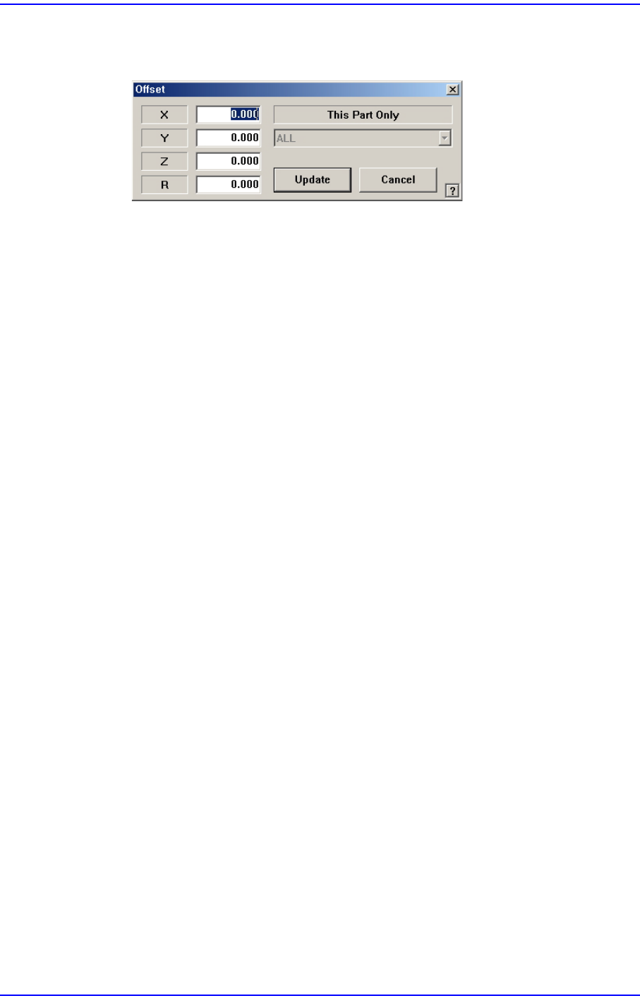
Apply the offset value to all parts.
<X> edit box
Set the X offset value.
<Y> edit box
Set the Y offset value.
<Z> edit box
Set the Z offset value.
<R> edit box
Set the R offset value.
<OK> button
Closes the dialog box and adds the set offset value to the selected line in the grid.
<Cancel> button
Ignores the set offset value and closes the dialog box
<Adjust…> button
It is a function used to change the PCB step coordinate or to check and adjust the gap
between the previous fiducial mark coordinate and the current fiducial mark
coordinate to use the previous step coordinate when the backup table is down
accidentally.
<Clear Cycle> button
Initialize the placement cycle.
<Refresh Feeder> button
When the feeder setup has been changed in the “feeder” dialog box, clicking this
button will allow the feeder changed in the “Step” dialog box to be set up again.
<Refresh Nozzle> button
When the nozzle arrangement on the ANC has been changed, clicking this button will
allow the nozzle changed in the “Step” dialog box to be set up again.
<Place Parts> button
This function is provided to perform testing in preparation for operation or to
compliment some placement points during operation. It is used to place parts at the
placement point selected from the <Step> dialog box.
9-10
Next Generation, Multi-Functional Placer DECAN S1 Administrator’s Guide
The number of placement points available with this function is maximum 150 points.
The conditions for enabling this button are as follows;
Login with authority level higher than that of the programmer
Completed PCB file download
PCB is loaded at the placement station on the conveyor.
<Parts Placed> check box
Select this check box to have placement work skipped for the corresponding part when
placing a PCB later by check-marking the placement point of the part, for which
placement testing has been completed, on the <PL> column using the <Place Parts>
button.
<POP Steps Only> check box
Selects only the placement point of the POP part among all placement points in order
to indicate it in the dialog box. This function can be used for the machine in which a
flux unit is installed.
<Semi Extend> checkbox
It only appears with Array PCB, and only the selected array step is displayed on the
Step screen while the step is in the Array Extend state.
Changing the teaching value of a certain array in the Semi Extend state changes the
teaching values matched with other arrays.
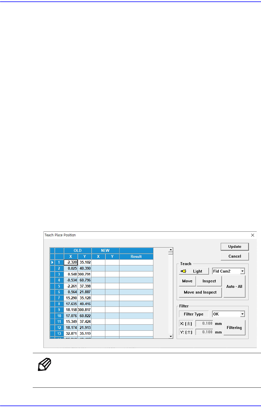
<Pos Tuning> button
It is used to automatically teach the mounting points of specific chip parts.
Memo The size of parts that can be taught with this function is 0402 to 3216
and is subject to change.
9-11
Step Programming
The step data generated by the fiducial camera of the instrument scans the pattern of
the bare PCB and the actual mounting position can be compared.
The basic usage scenarios for these features are as follows:
1)Prepare a PCB file with a registered mounting point.
2)Insert a blank PCB without soldering into the equipment.
3)In <PCB Edit>-<Board>, enter 'Initial Theta'.
4)Select the <Pos Tuning> button in <PCB Edit>-<Step> to create the <Teach Place
Position> window.
5)Scan each step using the <Inspect> or <Auto - All> function.
6)When the scan is complete, check the step where an NG has occurred using the filter
function, and select the <Move> and <Inspect> buttons to recognize the step
again.
7)Using the filter function, check if the coordinates of the scanned step are normal
compared to the existing step.
8)Select the <Update> button to apply as step data only up to the step whose 'Result' is
'OK'.
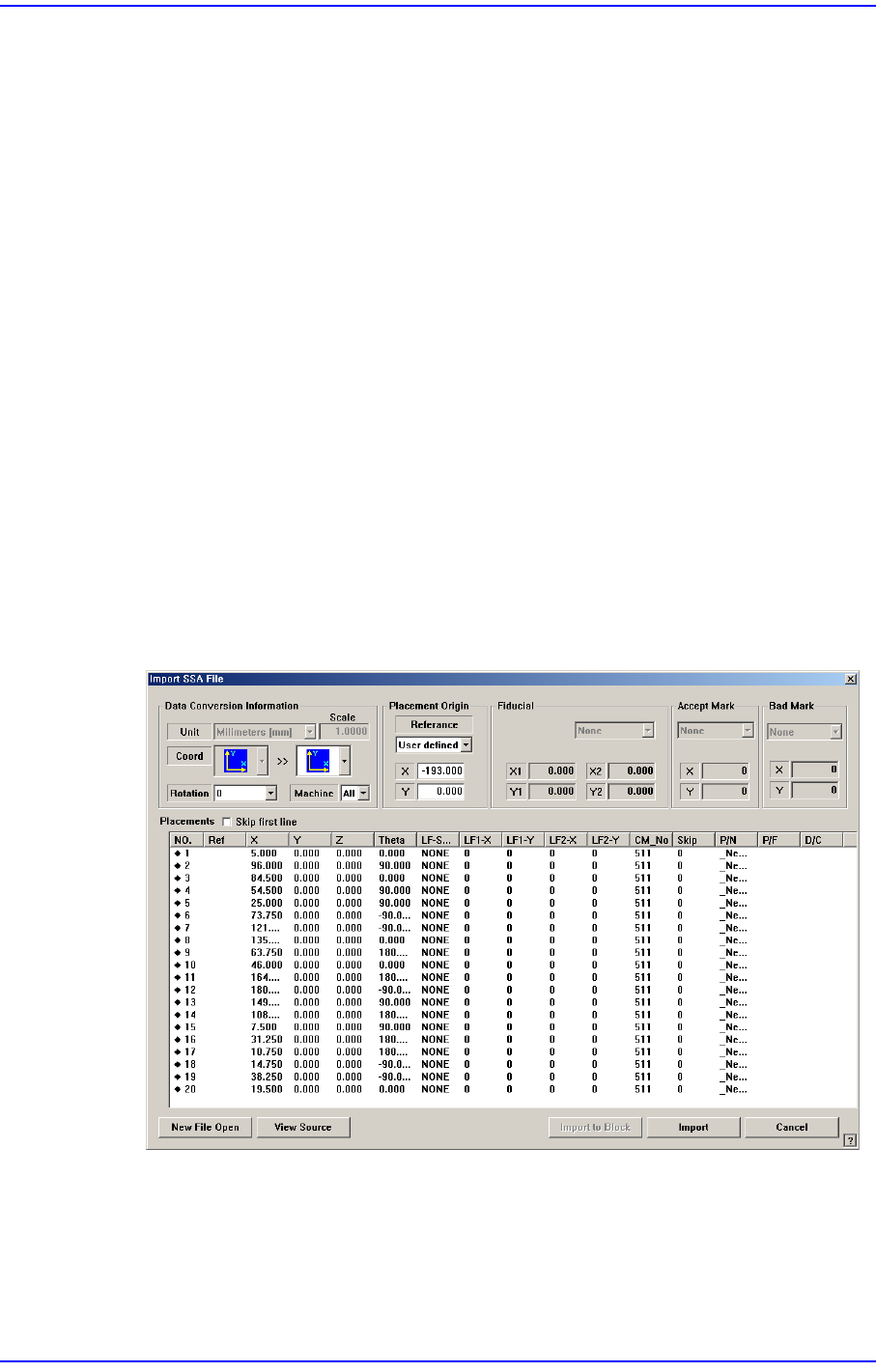
<Import…> button
Converts externally created ASCII data into step data for this machine.
If the <Import> button is clicked, the process that converts the corresponding data to
the step data is initialized.
Click the <Import> button in the <Steps> dialog box.