DECAN_S1_Administrator′s_Guide(Eng_Ver1.5)_Print.pdf - 第316页
10-4 Next Generation, Multi-Functional Plac er DECAN S1 Administrator’s Guide <Placements> column Displays the number of times each nozzle is used. In other words, the number of placement points using th e corres…
10-3
Optimization
this button. Then the number of <AVL> column becomes ‘2’.
Appropriate number of feeders must be set in consideration of the number of
placement points for each component. If the Optimizer considers that more than one
feeders are not necessary, it might not be used. .
To obtain good operation efficiency, a relatively large number of feeders must be
assigned to a component with many placement points.
button
Used to have the feeder selected in the <Arranged Feeders> list box to be arranged
again by Optimizer.
10.2. Nozzle
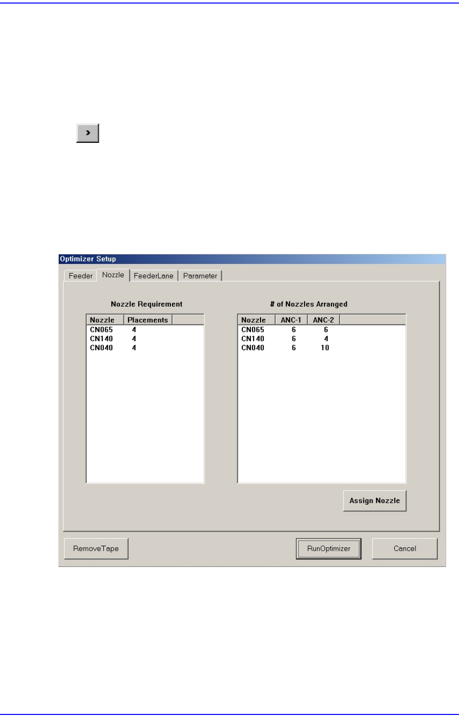
Figure10.2 “Optimizer Setup: Nozzle” dialog box
This dialog box shows the information on Nozzle arrangement.
<Nozzle Requirement> list box
This list box indicates the types of nozzles necessary for the part placement as well as
the number of times of use of each nozzle.
<Nozzle> column
Displays the nozzle name.
10-4
Next Generation, Multi-Functional Placer DECAN S1 Administrator’s Guide
<Placements> column
Displays the number of times each nozzle is used. In other words, the number of
placement points using the corresponding nozzle.
<# of Nozzles Arranged> list box
This list box indicates the types and number of nozzles that are arranged in each ANC
currently.
<Nozzle> column
Displays the nozzle name.
<ANC-1 ANC-2> column
Displays the ANC where the nozzle is arranged.
<Assign Nozzle> button
Used to assign applicable heads for each nozzle separately. When this button is clicked
on, the following dialog box is displayed.
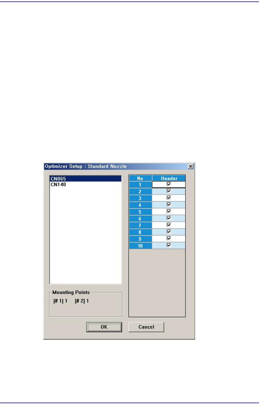
Figure10.3 “Optimizer Setup: Assign Nozzle” dialog box
Basically all nozzle types can be applied to any head, therefore all heads are checked.
But there are occasions when a certain nozzle has to be operated in a certain head.
Also, this can be used when the user wants to assign a certain head to a certain nozzle.
The above figure shows the nozzle CN065 can operate on any head between Head1
and Head10.

10-5
Optimization
<Useful Heads> check box group
The heads that can be used by the selected nozzle type. As a standard, check so that
Head1 ~ Head10 can be used.
<Mounting Points> group
This group shows the number of components used by the nozzle selected for the
current PCB. This can be used as a reference data when the user assigns the applicable
heads to each nozzle.
#1 shows the total number of placement points of the component for which #1 nozzle
is selected and #10 shows the total number of placement points of the component for
which #10 nozzle is selected.
Figure 10.4 shows that CN065 is selected for 1# nozzle of one components and for 2#
nozzle of one component.
<OK> button
Saves the selected options and closes the dialog box..
<Cancel> button
Cancels the selected options and closes the dialog box.