DECAN_S1_Administrator′s_Guide(Eng_Ver1.5)_Print.pdf - 第365页
13-13 Production Setup corresponding camera from the <Device> combo box. Head Selected when looking at the image in wh ich the part picked up by a specific head is recognized. Sele ct the corresponding head from …
13-12
Next Generation, Multi-Functional Placer DECAN S1 Administrator’s Guide
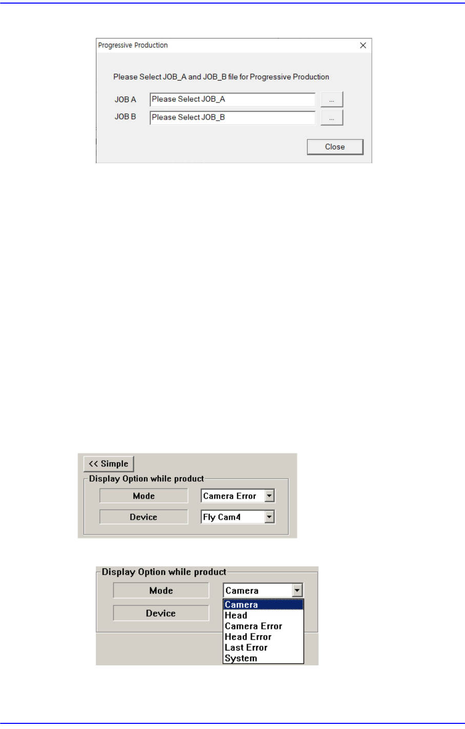
<SET> button
Scenarios for using this feature are as follows:
1)Prepare 2 PCB files that meet the above conditions.
2)Select the <Product>-<Option Setting>-<Progressive Product> check box and select
the <SET> button.
3)Load the PCB files you want to produce in JOB A and JOB B.
4)Open the PCB file to be produced first and start production.
At this time, check if it is displayed as JOB_A: the name of the PCB to be
produced first in the PCB information on top of MMI after downloading RT.
5)When PCB production is completed, use the Docking Change Dialog to connect the
docking cart to be used on the second PCB and select Continue.
At this time, check if it is displayed as JOB_B: the name of the PCB to be
produced second in the PCB information on top of MMI after downloading RT.
<Detail> button
This button is used to select the image viewed in the SMVision window during PCB
production.
<Mode> combo box
Camera
Selected when looking at the image of a specific camera. Select the
13-13
Production Setup
corresponding camera from the <Device> combo box.
Head
Selected when looking at the image in which the part picked up by a specific
head is recognized. Select the corresponding head from the <Device> combo
box.
Camera Error
Selected when looking at the image of part recognition error from a specific
camera.
It shows the recognized part image according to the placement order during
placement. However, if the placement is completed, the camera selected in the
following <Device> combo box shows the part image error that occurred last.
Head Error
Selected when looking at the recognition error image of part picked up by a
specific head.
It shows the recognized part image according to the placement order during
placement. However, if the placement is completed, it shows the image of part
recognition error that occurred last among the parts placed by the head
selected in the following <Device> combo box.
Last Error
It shows the recognized part image according to the placement order during
placement. However, if the placement is completed, it shows the image of part
recognition error that occurred last during placement.
System
Shows the part recognition image according to the placement order.
13-14
Next Generation, Multi-Functional Placer DECAN S1 Administrator’s Guide
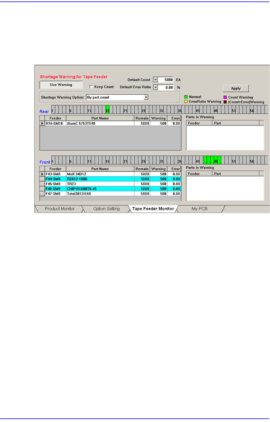
13.1.3. Tape Feeder Monitor
Sets the quantity of remaining components. It shows the remaining components of the
installed tape feeder and alarms against the component shortage. Able to monitor the
errors related with parts supply of tape feeder.
Figure13.5 “Tape Feeder Monitor” tab dialog
<Use Warning> button
Selects whether to automatically show the alarm message setup in the ‘Tape Feeder
Monitor’ tap dialog box while working. It is setup as ‘use’ in the above dialog box.
<Keep Count> check box
Generally, if the PCB program is downloaded, the remaining quantity is set up to the
default count.
In case the same PCB program must be downloaded again for a particular reason
during operation, select this check box to maintain the Remain Count of the tape
feeder installed already.
<Default Count> combo box
Indicates the part shortage alarm message box when the remaining quantity of parts
supplied to the tape feeder is less than the setup value.