DECAN_S1_Administrator′s_Guide(Eng_Ver1.5)_Print.pdf - 第386页
14-4 Next Generation, Multi-Functional Plac er DECAN S1 Administrator’s Guide 14.1.2. <Head Offset > Tap dialog box Setup the offset for the mechanical charac teristics of each head. The head offset information dis…

14-3
Machine Calibration
Used for moving the selected object to the assigned position of coordinates by
rotating XY, Z axis driving motor, or for obtaining the present coordinates of the
selected object.
Fid Cam1 ~ Fid Cam2
Select the Fiducial Camera.
Head 1 ~ Head 10
Select #1 ~ #10 spindles.
<Move> button
Move the object selected in the combo box to the position of the assigned
coordinates. At this time, before executing <Move> button, the edit box
corresponding to the desired position must be clicked on with a mouse.
<Get> button
Obtain coordinates for XY, Z axis with reference to the object selected in the
<Device> combo box. At this time, before executing <Get> button, the edit box
corresponding to the desired position must be clicked on with a mouse.
<Update> button
Transmits the set data to the machine and closes the dialog box.
<Cancel> button
Ignores the set data and closes the dialog box.
14-4
Next Generation, Multi-Functional Placer DECAN S1 Administrator’s Guide
14.1.2. <Head Offset> Tap dialog box
Setup the offset for the mechanical characteristics of each head. The head offset
information displayed here, with the exception of that for the Z and R axes is updated
automatically if the head offset calibration is executed during camera calibration and the
result value is reflected.
Caution Do not modify data in the actual placement of each head at
user’s discretion, as damage to head or defective work may
occur if the setup value has changed by the user when
placement is being performed based on the offset value.
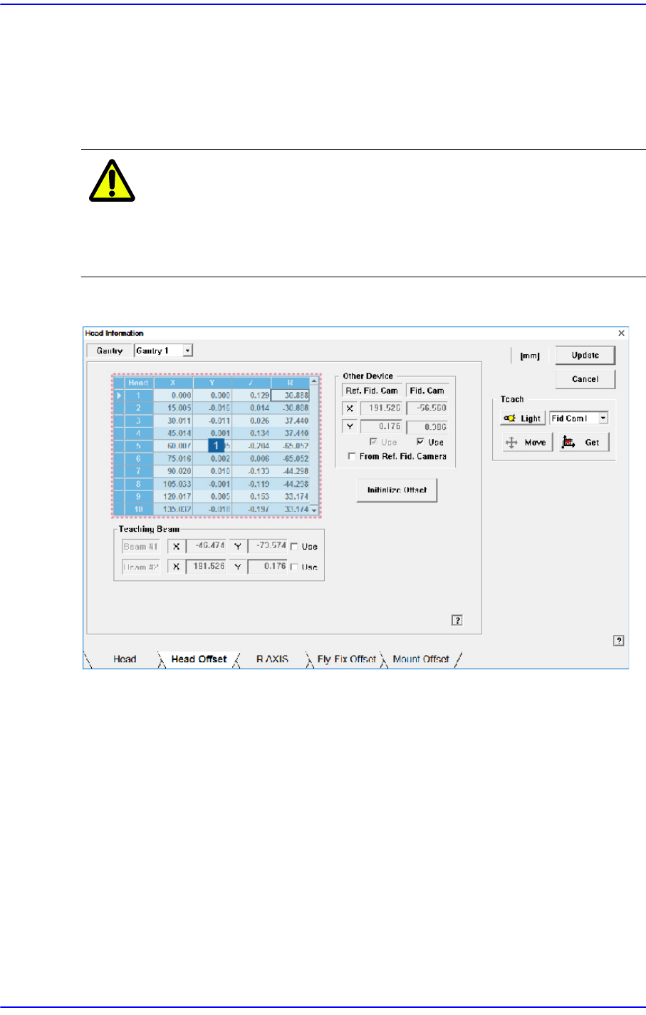
Figure14.2 “Head Offset” tab dialog
1: Grid group
<Gantry> combo box
Selects the gantry for which setup will be performed.
<Grid> group
Sets the offset between heads.
<Head> column
Displays the head number.
<X> column
Sets the X offset value. Set the X position of the head1 to 0 when the XY axes
reach home and set this value as a reference.
<Y> column

14-5
Machine Calibration
Sets the Y offset value. Set the Y position of the head1 to 0 when the XY axes
reach and set this value as a reference.
<Z> column
Sets the Z offset value. Set the PCB top surface as the reference of the offset value
when the PCB is loaded.
<R> column
Sets the R offset.
<Other Device> group
Sets the offset values of devices other than the head.
<Fiducial Cam> edit box
Sets the XY offset value of the Fiducial camera.
<From Ref. Camera> check box
Indicates the XY data in the ‘Grid’ group with the center of ‘Fiducial Camera 1’ as
a base.
<Teaching Beam> group
Sets the items related to the teaching beam (Height Sensor).
<X> edit box
Input the X coordinate of the teaching beam.
<Y> edit box
Input the Y coordinate of the teaching beam.
<Z> edit box
Input the Z coordinate of the teaching beam.
<Use> check box
Sets whether to use the teaching beam (Height Sensor). This function is enabled in
machines in which a height sensor is installed.
<Initialize Offset> button
This button is only displayed when you log in in “Service” mode. This is used to reset
the fiducial camera offset and head offset to their default values. When you click this
button, the following dialog box is displayed.
If you click the <Yes> button, the fiducial camera offset and head offset are set to their