DECAN_S1_Administrator′s_Guide(Eng_Ver1.5)_Print.pdf - 第390页
14-8 Next Generation, Multi-Functional Plac er DECAN S1 Administrator’s Guide 14.1.4. <Fly-Fix Offset> tab dialog Sets the Fly-Fix of fset for each head. Data in this d ialog box is upda ted automatically if the Fl…
14-7
Machine Calibration
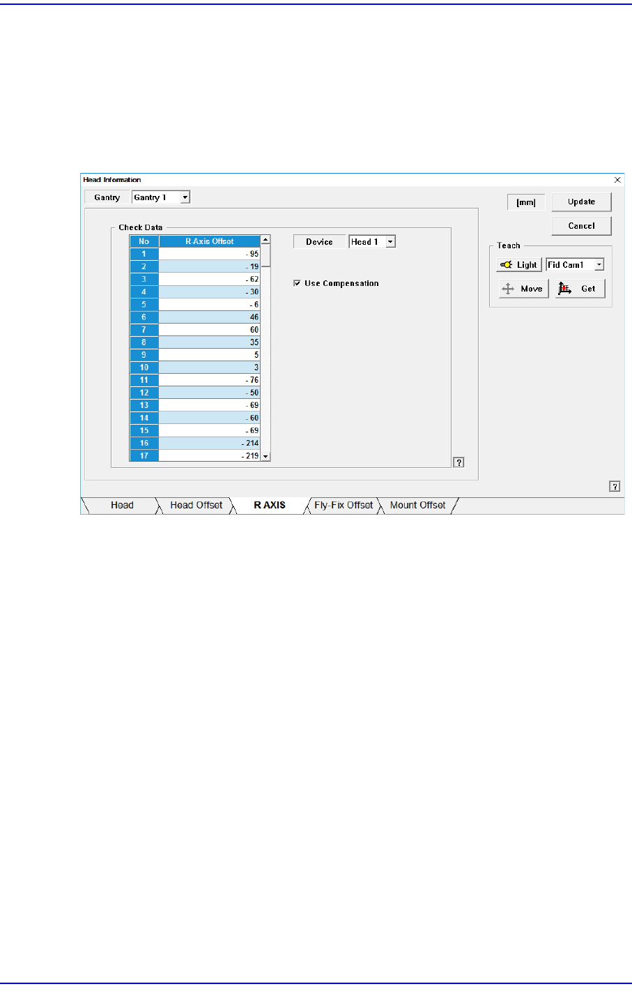
14.1.3. <R Axis> tab dialog
Displays the R axis compensation value of each head, or determines whether to
compensate the R axis. Data in this dialog box is updated automatically if the R-Axis
Offset Calibration is executed during camera calibration and the result value is reflected.
Setup whether to apply compensation on the R-axis of each head or not.
Figure14.3 “R AXIS” tab dialog
<Check Data> group
Indicates the R axis compensation value of each head.
<Device> combo box
Select the head.
<Use Compensation> check box
Determines whether to use the R axis compensation method for each head.
<Update> button
Transmits the change data to the equipment and closes the dialog box.
<Cancel> button
Ignores the change data and closes the dialog box.
14-8
Next Generation, Multi-Functional Placer DECAN S1 Administrator’s Guide
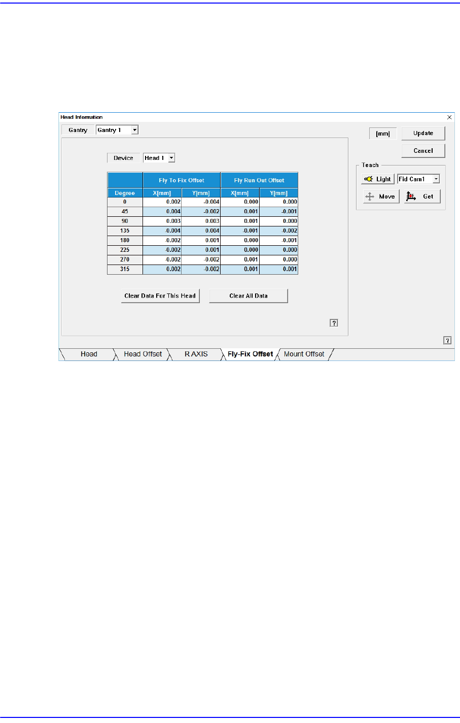
14.1.4. <Fly-Fix Offset> tab dialog
Sets the Fly-Fix offset for each head. Data in this dialog box is updated automatically if the
Fly to Fix Offset Calibration is executed during camera calibration and the result value is
reflected.
Figure14.4 “Fly-Fix Offset” tab dialog
<Device> combo box
Sets the Fly-Fix offset for each head.
<Fly To Fix Offset>
<Degree> column
Sets the Fly-Fix offset by degree at 45 degree interval.
<X, Y> column
Sets the Fly-Fix offset of X, Y.
<Fly Run Out Offset>
<Degree> column
Fly-Fix offset for each angle can be setup at the interval of 45 degrees.
<X, Y> column
Sets the Fly Run Out offset of X, Y.
<Clear data for this Head> button
Deletes Fly-Fix offset data of the selected head. Used when not applying the Fly-Fix
offset on the head. Data cannot be restored once it has been deleted. To apply the Fly-
Fix offset, the camera calibration must be performed again.
14-9
Machine Calibration
<Clear All Data> button
All Fly-Fix offset data can be deleted. Erased data cannot be restored. Camera
Calibration must be performed again to apply the Fly-Fix offset.
<Update> button
Transmits the change data to the equipment and closes the dialog box.
<Cancel> button
Ignores the change data and closes the dialog box.
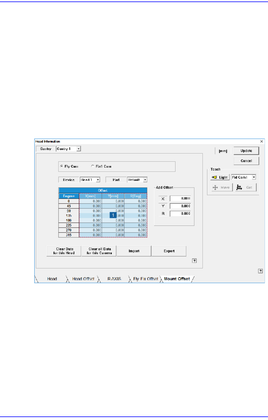
14.1.5. <Mount Offset> tab dialog
Sets the placement offset for each head / Part.
Figure14.5 “Mount Offset” tab dialog
1: Grid group
<Fly Cam / Fix1 Cam> option button area
Sets the placement offset for each camera.
<Device> combo box
Sets the placement offset for each head.
<Part> combo box
Sets the placement offset for each part.
<Grid> group
<Degree> column
Sets the placement offset by degree at 45 degree interval.